
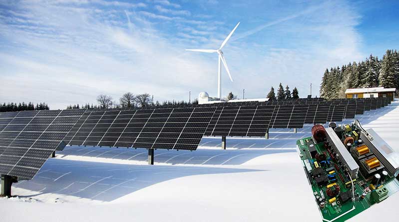
Printed circuit boards, or PCBs, connect and mount components on a circuit board, and different circuit boards connect each other to form a functional system, like a solar light system. Speaking of circuit boards for solar light systems, the LED PCBs in aluminum or FR4, or copper substrate to be used for the light itself is the least you want to learn about. The circuit boards used for the solar MPPT (maximum power point tracking) charging, battery packs, and DC-DC power conversion to the MCU control board, LED driver, and inverter board are what you are most interested in.
PCBONLINE, an OEM PCB manufacturer, provides one-stop circuit boards for solar light systems. In our article, we will explore what circuit boards for a solar light system are.
Solar Light System Circuits of Different Complexity Levels
As functional complexity increases, a solar lighting system is no longer a simple single-board solution but a multi-board system that works in coordination.
Solar light systems, from the simplest lawn lights to high-power road lighting systems, have different circuitry complexity levels. Whether simple or complex, its circuit is determined by its application and quality tier.
There are basic lawn solar lights, household lights of medium complexity, and off-grid and solar street lights of the advanced tier.

Basic Lawn Solar Lights Circuit
A solar lawn light system using direct current (DC) is the most basic and cheapest, featuring a simple circuit.
Its circuit consists of:
- Solar panel for DC power generation (typically 2V to 6V),
- Charge control, whose simplest form uses a diode to prevent reverse current flow,
- Battery, usually 1 cell Ni-MH or 1 cell lithium,
- Light control switch, which detects ambient light intensity and automatically turns on at dusk
- LED driver for simple current limiting or boost conversion)
It requires no battery management system (BMS), no inverter module, no control IC, but only uses a photoresistor + MOS/transistor. Small and single-layer circuit boards are enough for this simple solar light circuit. Sometimes, it requires only a small PCB on the back of the solar panel.
The focus of the circuit board for the basic lawn solar circuit is the LED driver and light control section, but the overall circuit is still simple.
Household Solar Lights of Medium Complexity
A household solar light system requires charge management and battery management, so its circuit requires smarter control and protection.
Its circuit includes:
- Solar panel for PV input,
- Charge management module (MPPT or PWM),
- Lithium or LiFePO4 battery pack,
- BMS module for overcharge, over-discharge, and overcurrent protection,
- DC-DC conversion circuit, Boost/Buck for the LED,
- Light control + time control + Microcontroller (MCU),
- LED constant current driver providing high efficiency and stable brightness
A household solar light system requires multiple circuit boards for charge, protection, control, and an LED driver, and the control board manages energy and logic control. However, it is still a DC system without an inverter.
The focus of circuit boards in this solar light system is the control boards, which include solar charge management, battery BMS, and lighting control logic. The LED light PCB is merely the end-point carrier.
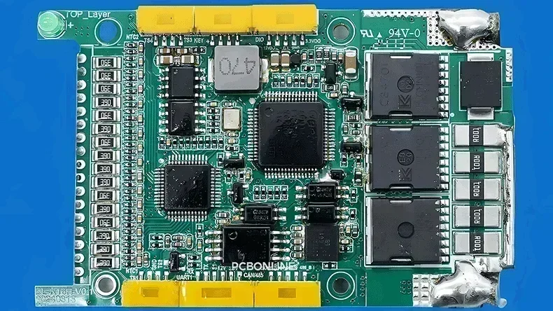
BMS circuit board made by PCBONLINE
Off-Grid and Solar Street Lights of the Advanced Tier
An off-grid solar light system, such as solar street lights, is a complex architecture with a complete circuit that closely resembles a mini-PV system.
Such an advanced off-grid solar light circuit includes:
- Solar panel array from 18V to 36V or even higher,
- MPPT charge controller to achieve maximum efficiency charging,
- Battery pack with a cell connection system (CCS), a BMS, and multi-series Lithium or LiFePO4 cells,
- DC-DC converter or DC-AC inverter (some may even output 220V),
- Load drive control for smart dimming, timing, and remote communication,
- Communication and sensing (LoRa, illumination, temperature, current detection, etc.)
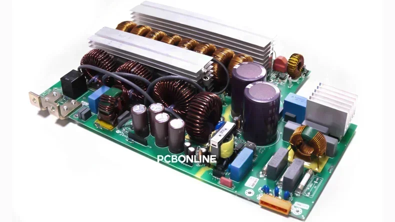
Inverter circuit board made by PCBONLINE
The PCB design of the circuit boards for the off-grid solar light system has quite a lot to focus:
- Safety isolation between the high-voltage DC input and the buck circuit,
- Copper thickness design and thermal management for high-current paths, for example, PCB busbar,
- Integration of MCU control logic, power management unit, and BMS interface
- Electromagnetic compatibility (EMC) and lightning protection design
Still, the main control circuit boards, including charge control, energy management, and BMS interface, are the core circuit boards. The LED light PCB and solar panel are merely peripheral modules.
For a straightforward overview of the different solar light circuitry, here's a table.
|
Solar light
|
Circuit Complexity
|
PCB focus
|
BMS used?
|
Inverter used?
|
|
Lawn light
|
★☆☆☆☆
|
Light control + LED current limit
|
No
|
No
|
|
Garden light
|
★★★☆☆
|
Charge management + BMS + driver
|
Yes
|
No
|
|
Street/off-grid light
|
★★★★★
|
MPPT + BMS + MCU control
|
Yes
|
Yes
|
Circuit Boards for Mid to Advanced Solar Light Systems
What are the circuit boards used in household or street solar light systems? PCBONLINE manufactures and assembles these high-current PCBAs used for solar systems, and below is our explanation of these circuit boards.
|
Circuit board
|
Function
|
Required?
|
Description
|
|
Solar charging/MPPT
|
Receives input from the solar panel, regulates charging current and voltage, and manages efficient charging of the battery
|
Yes
|
Core power interface between solar input and the battery; often implements MPPT
|
|
BMS
|
Monitors cell voltages and temperature; provides overcharge, overdischarge, and balancing protection
|
Yes
|
Usually, a separate PCBA for the multi-cell battery pack to communicate with the control board
|
|
Connects cells and the BMS, transfers cell voltages and temperature signals to the BMS, and provides balance lines
|
Yes
|
Soldered with the cells in the battery pack, and is customized
|
|
|
DC-DC power conversion board
|
Converts the battery output (e.g., 12V or 24V) to the voltage or current required by the LED driver
|
Yes
|
Ensures stable power delivery; often includes high-efficiency converters and EMI filters
|
|
LED driver
|
Provides constant-current driving for LED arrays, manages brightness and efficiency
|
Yes
|
Maybe an independent board for better heat management, especially at higher power levels
|
|
Main Control/MCU board
|
Handles logic control (timing, light sensing, dimming, communication)
|
Yes
|
The "brain" of the system, typically built around a microcontroller or SoC with RTC and sensor interfaces
|
|
Communication/sensor board
|
Provides sensors (light, temperature) and wireless communication (LoRa, Bluetooth, etc.)
|
Optional
|
Sometimes integrated into the main board
|
|
Inverter Board
|
Converts DC power from the battery into AC (e.g., 220V)
|
Optional
|
Used only when AC loads are needed
|
|
Display/interface board
|
Displays system status (voltage, power, charging) or provides button interfaces
|
Optional
|
Common in advanced or portable power systems
|
A typical solar light system architecture is as follows.

What about the electrical relationships between the different circuit boards for the solar light system? You can check the following table.
|
Circuit board
|
Voltage level
|
Signal type
|
Communicates with
|
|
Solar charging/MPPT
|
12–36V DC input / charging current control
|
Analog / I²C / UART
|
BMS, MCU
|
|
BMS
|
3.6–48V (depending on battery configuration)
|
Analog / I²C
|
MCU, CCS
|
|
CCS
|
3.6–48V (depending on battery configuration)
|
Analog
|
BMS, cells
|
|
DC-DC power conversion board
|
Regulated outputs (5V, 12V, 24V)
|
Power output
|
LED Driver / MCU
|
|
LED driver
|
Constant current output (350mA–3A)
|
PWM dimming
|
MCU
|
|
Main control/MCU board
|
Logic and communication (3.3V or 5V)
|
Digital signals
|
All modules
|
|
Inverter board
|
DC input → AC output (12V → 220V)
|
Power output
|
AC load
|
Depending on the solar light system types, the number of circuit boards for a solar light system ranges from three to eight.
- Medium-power solar light (20–40W): 3–4 circuit boards, and they are MPPT + BMS + LED driver + control board.
- Smart garden/integrated streetlight (50–100W): 4–6 circuit boards, and they include an MCU, a light sensor, and a DC-DC conversion board.
- Off-grid solar lighting system (>100W or with AC output): 6–8 circuit boards, which include an inverter and communication boards.
Partner with PCBONLINE for One-stop Circuit Boards for Solar Lights
PCBONLINE is committed to PCB manufacturing and assembly for solar, not only solar energy devices like solar light systems. We are especially good at high-current PCBAs because we have rich experience in thermal management and large/small current separation.
Founded in 2005, PCBONLINE has two large advanced PCB manufacturing bases, one PCB assembly factory, stable supply chains, and an R&D team to provide you with solar light system circuit boards under one roof.
PCBONLINE has strong PCB manufacturing and assembly capabilities and rich technical experiences for devices that require high current carrying and great thermal dissipation, including BMS, CCS, PV inverters, inverters, and charge controllers.
PCBONLINE manufactures various high-thermal-conductivity PCBs, including thick-copper PCBs up to 14oz, copper-based PCBs, hybrid-laminated PCBs, ceramic PCBs, etc.
We can inlay and solder copper busbars in various PCBs and solder terminal blocks, and optimize trace width/space to increase PCBA current-carrying capacity.
In R&D, PCBONLINE excels in thermal dissipation design and electrical management, and we also take care of details in mold design, reflow/wave soldering oven temperature control, and production flow design.
You can have high-current PCBAs for solar energy and EVs manufactured at PCBONLINE from prototypes to batch production, including PCB fabrication, PCB assembly, component sourcing, IC burning-in programming, PCBA value-added, enclosures, and box-build assembly.
We offer free R&D, samples, and PCBA functional testing for high-current PCBA bulk production orders.
High-quality PCBA manufacturing certified with ISO 9001:2015, IATF 16949, RoHS, REACH, UL, and IPC-A-610 Class 2/3.
The PCBA manufacturing process, faculty, time, specs, and all materials are traceable for 15 years for quality traceability.
If you want to get R&D assistance or get a quote for your solder light systems, PCBONLINE is pleased to receive your message and provide help and PCBA manufacturing services. Please email info@pcbonline.com to reach out to us. We will provide one-on-one engineering support throughout your project.
Conclusion
Circuit boards for a medium to high-end solar light system include a BMS for battery protection and monitoring, a solar MPPT board for power regulation and charging control, a DC-DC conversion board for power conversion, an LED driver board for constant-current output to LEDs, and a main MCU control board for system logic and coordination. PCBONLINE is proud to lead the high-current PCBA manufacturing for solar energy applications. Contact us to order our turnkey circuit boards for solar lights and see how we can support your green energy initiatives.
PCB assembly at PCBONLINE.pdf
Battery Management System Manufacturing at PCBONLINE.pdf
CCS Product Introduction - PCBONLINE.pdf


