
Renewable energy is reshaping the use of energy to power our lives. Renewable energy can be in the form of solar or wind energy, stored in battery packs or any other form. The DC-to-DC converters enable them to work properly and reliably. These converters make the solar panels, wind turbines, and battery packs work together seamlessly.
Designing a good power Printed Circuit Board (PCB) is important. Let's deeply go through the concept of DC-to-DC converters, their applications, and discover why partnering with a trusted PCB manufacturer like PCBONLINE is the key to unlocking the full potential of renewable energy sources.
Purpose of DC-to-DC Converters
DC-to-DC converters either step-up (Boost), step-down (Buck), or step-up/down (Buck-Boost) the DC voltages to a specified level depending on our circuit needs.
Our household electronics operate at different voltage levels. The electronic equipment needs sources that match their specific Voltage and Current requirements to properly turn them ON.
The DC-to-DC converters here fill this gap and make our equipment work efficiently without malfunctioning. These converters transform one DC voltage level to another, ensuring that the electronics system, whether it is in our smartphones, electric vehicles, or solar/wind energy systems, receives the precise power it needs to operate.
Renewable energy sources like solar panels and wind turbines provide variable outputs. DC-to-DC converters are critical for managing these varying outputs and delivering stable output power.
The purpose of DC-to-DC converters is simple yet profound: to regulate voltage efficiently while minimizing energy loss. DC-DC converters are the backbone of modern power electronics. The quality of PCB selected to fabricate DC-to-DC converters defines their performance and reliability. PCBONLINE specializes in crafting high-performance PCBs tailored for renewable energy systems, ensuring reliability and efficiency.
DC-to-DC Converter Types
There are many topologies of DC-to-DC converters. Specific voltage regulations require implementing a specific topology. The following are the most common converter topologies:
Buck converters
They step down the incoming voltages to a lower level. Mostly used where the load operates at lower voltage levels as compared to the input. For example, in solar energy systems where we get like 40V output from solar panels during a full sunny day, the buck converter steps down to a 12V level, which is suitable for charging our batteries. Battery Management Systems (BMS) for charging battery packs use these converters as they provide high efficiency, which is ≥ 90%. Converting high-level to a low-level causes heat dissipation, so a careful PCB design is mandatory to manage the dissipated heat to ensure stable operation.
Boost converters
They step up the lower input voltages to higher output voltages. These are used when source voltages are insufficient for operating the load. For example, when wind flow is very low, the wind turbines' output drops to low voltages, and a boost converter is used to step up the voltage to meet battery charging requirements. When we step up the output, the input current increases to keep the input and output powers equal, so a robust PCB layout is necessary that minimizes the losses.
Buck-boost converters
They either step down or up the input voltages according to the load needs. In solar energy systems, whenever the output fluctuates due to varying atmospheric conditions (cloudy or sunny day), buck-boost converters ensure a stable voltage for battery charging. They provide flexibility but have increased complexity as compared to buck and boost topologies. Careful and precise PCB design and manufacturing are required for their optimum performance.
Ćuk converters
They either step up or step down the input to a reverse polarity output. They offer better immunity to EMI and are used in industrial automation and data centers.
SEPIC converters
These converters step up or step down the input voltages to positive voltages with a continuous input current flow.
Isolated converters
These converters use transformers to isolate the input from the output. Galvanic isolation is used to prevent a direct connection between the input and output. A transformer delivers energy to the output through a magnetic field instead of a direct conductive electrical path. This isolation provides noise reduction and hence safety to critical systems by separating output from input. Isolated converters are mostly used in industrial control systems, medical devices, and renewable energy systems.
Full-bridge converters
These converters are used in high-power applications, often in industrial and renewable energy systems.
DC-to-DC Converters
Each of these topologies has its own pros and cons, and their use depends on the circuit needs. For renewable energy systems like solar and wind energy and battery packs, buck, boost, and buck-boost converters are particularly used due to their reduced complexity, while also time with versatility and greater than 90% efficiency. High-quality PCB design is crucial to ensure their performance and reliability, especially under the variable conditions of solar and wind energy systems.
Understanding Buck, Boost, and Buck-Boost Converters
These are the most commonly used topologies of DC-to-DC converters. Buck, boost, and buck-boost are switching regulators that imply the use of transistors (MOSFETs) as switching components to produce the desired output. They offer higher efficiency and greater current handling than linear regulators. The major components and functionality of each of them are given below.
Buck converter
Key components:
- Input voltage source (Vin): Provides a higher-level input to be stepped down.
- Transistor switch: Usually, a MOSFET is used as a switch, controlled by a PWM signal to regulate the output.
- Inductor: Stores energy and handles high current.
- Freewheeling diode: Provides a current path when the MOSFET switch is OFF.
- Filtering capacitors: Filter input and output voltage ripples.
- Load: The circuit being powered, connected to Vout.
- Passive components (e.g., resistors for biasing).
operation:
- Current flows from Vin through the inductor to the load when the MOSFET is ON, storing energy in the inductor.
- The inductor releases the stored energy through the diode to maintain current flow when the MOSFET is OFF.
- The PWM duty cycle controls the average output voltage (Vout < Vin).
- Vout = Vin*D, where D is the duty cycle and is less than 1.
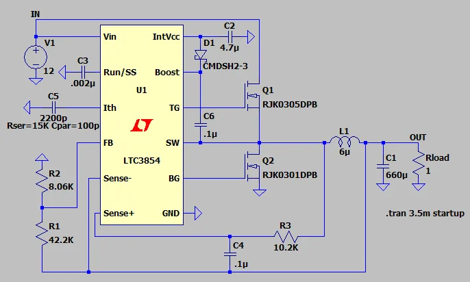
LTC3854-based switching Buck-Converter example schematic
Boost converter
Key components:
- Input voltage source (Vin): Provides the lower-level input to be stepped up.
- Transistor switch: Controlled by a PWM signal to regulate the output.
- Inductor - Stores energy when the switch is ON and releases energy when the switch is OFF.
- Freewheeling diode: Blocks reverse current and allows current flow to the output when the switch is OFF.
- Filtering capacitors: Filter input and output voltage ripples.
- Load: The circuit is being powered at a higher voltage, connected to Vout.
- Passive components (e.g., resistors for biasing).
operation:
- The diode blocks output, and the inductor charges from the input source when the switch is ON.
- When the switch is OFF, the inductor voltage adds to the input voltage (boosts), and current flows through the diode to the output.
- Vout = Vin / (1 – D), where D is less than 1.
LTC3429-based switching boost converter example schematic
Buck-boost converter
Key components:
- Input voltage source (Vin): Provides the input voltage to be regulated.
- Transistor switch: It isolates the input and output during switching and controls the energy transfer.
- Inductor: Stores energy from the input when the switch is ON and releases energy to the output when the switch is OFF.
- Freewheeling diode: Provides a current path from the inductor to the output during switch OFF.
- Filtering capacitors: Filter Vin and Vout and maintain Vout during switching.
- Load: The circuit is being powered through Vout with inverted polarity.
- Passive components (e.g., resistors for biasing).
Operation:
- Inductor charges from the input, output is isolated, running on a capacitor, during the switch ON state.
- Inductor discharges through the diode to the output when the switch is OFF.
- The output voltage can either be high or low compared to the input, but with inverted polarity.
- Vout = -Vin × D/(1-D), where D can be greater than or less than 1.
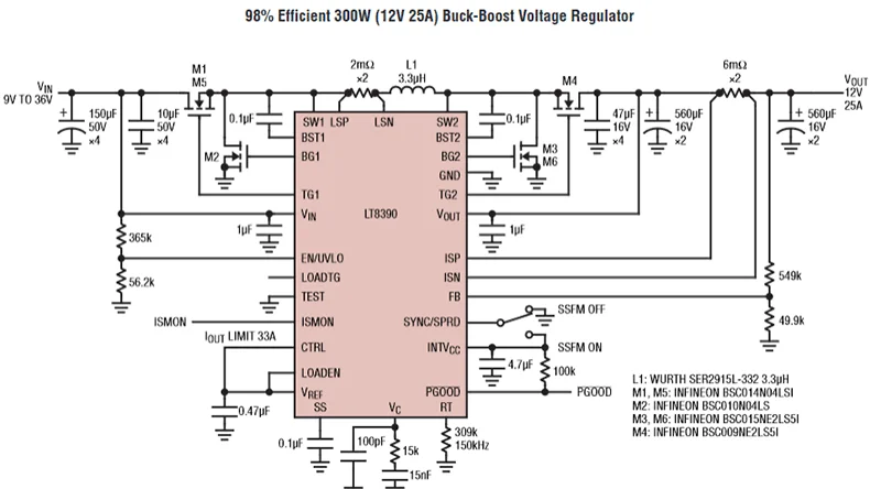
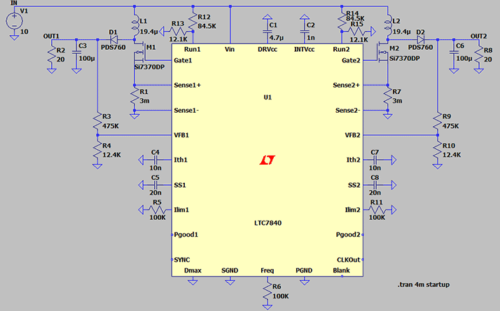
LT8390-based switching Buck-Boost Converter example schematic
Role and Applications of DC-to-DC Converters
As discussed earlier, DC-to-DC converters are the backbone of modern electronics. The renewable energy systems' operation heavily depends upon the use of these converters to step up/down the input voltages and to regulate the battery packs' charging to increase their lifespan.
Solar and wind energy systems
Solar panels generate varying voltages depending on the intensity. Similarly, wind turbines generate fluctuating voltages depending on the wind flow. These varying voltages can cause damage to our household electronics if fed directly without regulation. Voltage regulation is also necessary for grid integration.
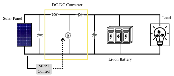
Solar Energy System Working
This image shows the DC-to-DC conversion of solar energy to charge the batteries and provide regulated DC power to household loads.
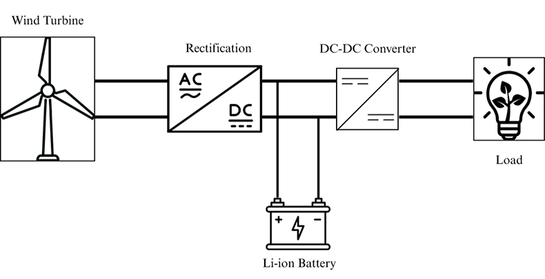
Wind Energy System Working
This image shows the conversion of energy, 1st rectification (AC-DC conversion), and that DC is used to charge batteries, and a further DC-to-DC converter regulates these voltages to power up the load.
Battery packs
Battery packs contain rechargeable batteries connected in series and parallel combinations that provide backup in the absence of solar and wind power. The regulated charging of these packs is necessary so that they can be charged to their rated voltages. The BMS works with DC-to-DC converters to prevent over-charging and keeps all the cells at the same level, expanding their lifespan and optimizing the energy storage. A buck converter regulates the input voltage to charge battery packs, and the boost converter then regulates to provide specific voltages to particular loads.
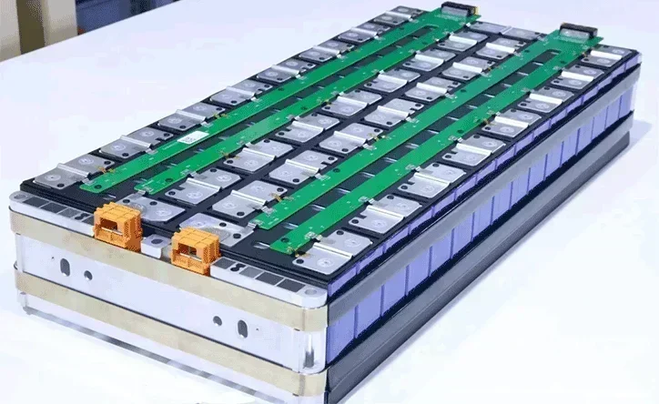
Battery Packs
The reliability of these applications depends on the quality of the PCBs on which the converters are manufactured. At PCBONLINE, we provide turnkey PCB fabrication and assembly services, ensuring that your DC-to-DC converters perform flawlessly in renewable energy systems.
Challenges and Solutions in PCB Design for DC-to-DC Converters
Based on the above discussion, designing PCBs for DC-to-DC converters requires careful consideration. The better the power PCB, the better the system performance. Some of the issues and their solutions faced during Power PCB design are as follows.
Components selection:
Selecting components depends on the application requirements of the converter. If a converter circuit is required to step down voltages to operate microcontrollers/processors, then we select small but better temperature components (e.g., automotive grade). But when we are designing a converter circuit for power supplies with ratings of many Watts, then bigger size components are selected as they can handle more heat effectively. "The larger the component, the better the power handling".
Thermal management:
DC-to-DC converters change the input voltage level to a different output voltage level, converting the excess voltages to heat. Switching of MOSFETs at high frequencies also generates heat. In addition to these heats, these PCBs have to handle high current requirements, hence causing more heat dissipation. This heat if not catered well, is definitely going to affect analog, digital, and RF parts of the circuit and the system overall, thus compromising the performance. Poor thermal management can lead to component failure and reduced efficiency.
Solution:
- Selecting the PCB material with good thermal properties.
- Selection of PCB copper thickness for PCBs like 1oz, 2oz, or 5oz for very high current requirements.
- Designing the PCB with optimized component placement and choosing a layer-stackup that handles the current and thermal requirements.
- Selecting components of good rating that can perform under these high heat conditions.
EMI/EMC management:
Electromagnetic interference (EMI) and electromagnetic compatibility (EMC) issues can lead to converters' operation to failure and affect other electronics operating on their output.
Solution:
- Ensure proper shielding of components/circuit parts like digital, analog, and power.
- Ensure proper grounding by using ground planes. Keep return loops/paths close and small.
- Carefully route tracks that can be affected by EMI.
- Follow industry standards to minimize EMI and meet system requirements.
Stability:
For the system to perform well and reliably, the power supplies/converters need to be stable, even under fluctuating input conditions. Component selection and circuit layout are critical in maintaining stability.
Choosing PCBONLINE for PCB Manufacturing and Assembly
When it comes to DC-to-DC converters for renewable energy systems, the success of your project depends on the quality of your PCBs.
PCBONLINE stands out by providing turnkey solutions from PCB design to fabrication and assembly. We handle every step with precision and expertise, saving your time and resources. Our advanced PCB design tools and one-on-one engineering support team work closely with you to understand your project's unique needs, providing tailored solutions for optimal performance and ensuring precise layouts and high-quality components for consistent performance.
Founded in 1999, PCBONLINE has two large advanced PCB manufacturing bases, one turnkey PCB assembly factory for power PCB assembly and box-build assembly, stable material and component supply chains, strategic cooperation with the mainstream MCU manufacturers, long-term cooperation with the top 3 fixture and enclosure manufacturers in China, and an R&D team for project development and DFM (design for manufacturing).
Our Design for Manufacturability (DFM) services ensure that every PCB is optimized for production with reliability and cost-effectiveness.
Power PCB manufacturing and assembly capabilities for DC-to-DC converters from prototypes to mass production, including high-current PCBs 3oz to 14oz, high-Tg PCBs, PCBs with busbars, etc.
PCBONLINE has rich experience in power modules and can do the R&D or take part in the development for your DC-to-DC converter project, providing the optimum PCB design, reducing fabrication cost.
PCBONLINE pays attention to all details, such as mold/fixture design, reflow/wave oven temperature controls, and fabrication process design, and does well in high-power and high-current PCBs for power applications like DC-to-DC converters.
High-quality PCB/PCBA manufacturing meeting your application demands, including ISO 9001:2015, ISO 14001:2015, IATF 16949:2016, RoHS, REACH, UL, IPC-A-610 Class 2/3, and IPC-A-610 Class 2/3.
When your order goes to the massive production stage, PCBONLINE refunds the fees of R&D, prototyping, components of the prototypes, and offers free PCBA functional testing.
No matter what quantity you want, we always prioritize quality and provide service and support that meet and exceed your expectations.
PCBONLINE has rich R&D and EMS manufacturing experience in battery pack modules for automotive and renewable energy systems. You can send your project request to PCBONLINE and get a quote by sending emails to info@pcbonline.com.
Conclusion
DC-to-DC converters enable efficient power management for solar panels, wind turbines, and battery packs. At PCBONLINE, we're committed to delivering high-performance PCBs that meet the unique demands of DC-to-DC converters in renewable energy applications. Ready to power your next renewable energy project with cutting-edge DC-to-DC converters? Partner with PCBONLINE for turnkey PCB manufacturing and assembly services that exceed your expectations.
PCB assembly at PCBONLINE.pdf


