
An inverter is a device that converts DC power to AC. It does the reverse work of a power supply, which converts AC to DC.
In this article:
Part 1: Application of Inverters Part 2: AC vs DC Part 3: 3 Types of Basic Inverter Circuits and How They WorkApplication of Inverters
Inverters are used in household energy storage (especially solar inverters), electronic vehicle (EV) motors, industrial photovoltaic (PV) inverters to provide power for factory equipment, grid-connected photovoltaic power generation, etc.
At home, we use AC power to run our appliances, which operate at 220V/110V and 50Hz/60Hz. The appliances that work on AC power cannot run on a DC source. Therefore, in houses using solar energy, we require inverters that convert the DC power from the battery to alternating AC power to run the AC appliances. The battery drainage depends upon the power rating of the AC appliance.
In an EV, the motor drives the wheels. The motor uses AC power, and the power of the motor comes from the battery pack, but the power battery stores DC power. The function of the inverter is to convert DC power into sine wave AC power, and it also controls the speed and torque of the AC motor.
The advanced electronics manufacturer PCBONLINE provides one-stop printed circuit board (PCB) fabrication and assembly for all kinds of inverter boards and engineering support. We reveal the basics of inverter circuits so you can design an inverter.
Besides, consumer electronics like wireless earbud boxes, portable power stations, and smartphone batteries also use inverters.
AC vs DC
Before discussing inverter circuits, let's first discuss the nature of alternating current and direct current and the requirements for converting from DC to AC.
DC
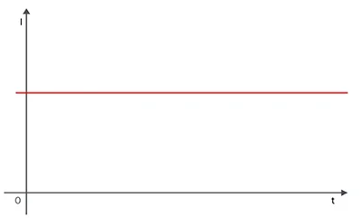
Direct current is unidirectional and flows from one terminal of the power source to the other. It flows due to the motion of electrons. Conventionally, we assume it flows from positive to negative. The alternating current only refers to the voltage of the power source's potential difference.
Generally, we get direct current from batteries and solar panels.
The direct current has a few drawbacks, it cannot be transferred to long ranges due to power losses.
AC
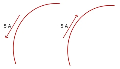
The alternating current changes its polarity with time. Once we define current as the movement of charge, we expect current to have an associated direction of flow. As mentioned earlier, the direction of current flow is conventionally taken as the direction of positive charge movement. Based on this convention, a current of 5A may be represented positively or negatively, as shown in Figure. In other words, a negative current of −5A flowing in one direction, as shown in Figure, is the same as a current of +5A flowing in the opposite direction.
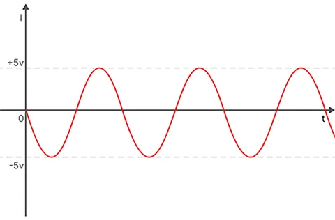
The graph of an alternating current is a sinusoidal waveform since it continuously changes from positive to negative.
The formula for alternating current is:
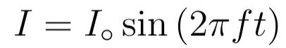
Here, t is the time, and f is the frequency in hertz.
3 Types of Basic Inverter Circuits and How They Work
As we have seen, the direct current graph is a straight line parallel to the time axis, and the alternating current has a sinusoidal waveform. Therefore, the inverter has to convert the constant DC to a fluctuating alternating current with a frequency of 50Hz. By the use of different electronic components we can convert the constant AC to sinusoidal waveform. The difference that will be seen from different circuits is the efficiency of power. Some circuits will generate a waveform almost similar to the sine wave with the same frequency, but the power output will vary.
Inverter Circuits By 555 times IC
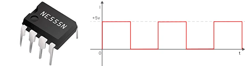
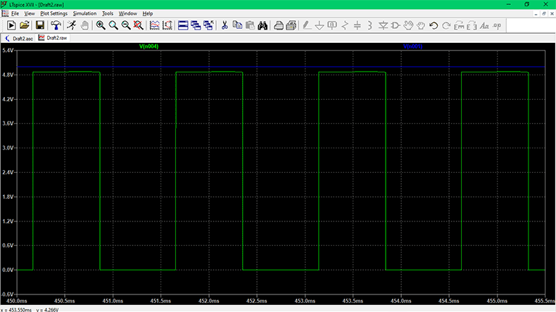
The 555 times IC can create a square wave with a 50% duty cycle in astable multivibrator mode.
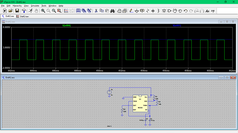
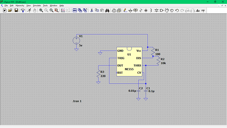
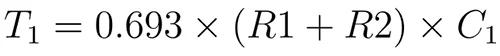
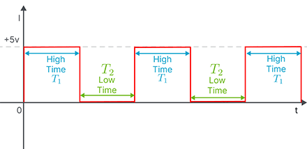
The time during which the waveform remains on a high level of the voltage is known as high time. The below formula can calculate the high time.
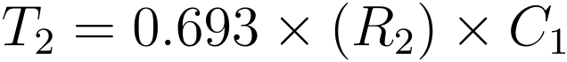
The time during which the waveform remains at a low voltage is called low time. The formula for calculating low time is below.
After calculating the high time and the low time calculate the duty cycle by the following formula.

Calculate the frequency of the generated wave by the formula.
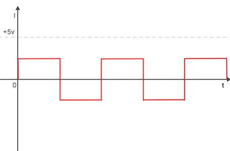
Since this square waveform starts from 0 volts and achieves a peak level of 5 volts, therefore it is not similar to the sinusoidal waveform, which changes its polarity from positive to negative. Hence, we will use a clamper circuit after this to shift the phase of this waveform.
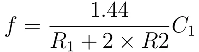
The clamper circuit is used to shift the waveform to a specified level. It is a circuit made with a combination of capacitor and diode. If the waveform is to be shifted to a positive level, then a positive clamper is used. A negative clamper is used to shift the waveform in the negative voltage direction or even below the 0v level.
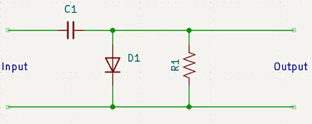
In this case, a negative clamper has been used to shift the waveform below 0v. Upon shifting the waveform with the negative clamper circuit, it will look similar to the one shown below.
At this stage, we have only got the square wave, but for AC we need a sine wave or modified sine wave. Therefore, we use a three-stage low-pass filter.
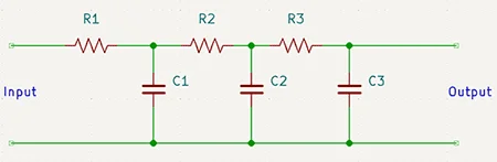
After using a passive RC filter, the waveform becomes the blue-colored wave shown below.
In this way, we can get a sinusoidal waveform by using a 555 timer IC and some other basic components. After this, we use a 12-0-12 center-tapped step-up transformer to make it 220 volts.
Conclusion and drawbacks of 555 timer inverterThe voltage level of the waveform drops after the clamper circuit. The output from pin 3 of the 555 timer is below 5v. After using the clamper circuit, the voltage level drops to half of the previous state. Therefore, many amplification circuits comprising transistors are used to amplify the voltage level.
This kind of inverter can only visualize the sinusoidal waveform on the oscilloscope and cannot be used to run appliances due to noise and low voltage levels.
Inverter Circuit with CD4047
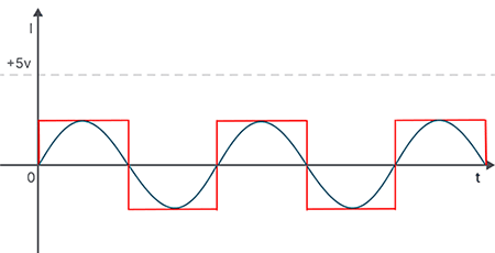
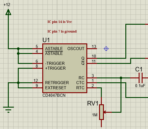
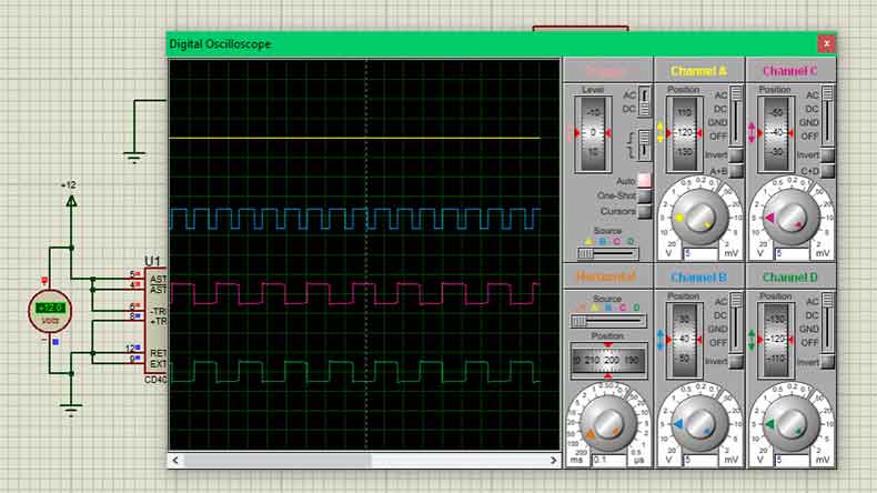
As seen in the case of the 555 timer inverter, there were many drawbacks. Therefore, use can use CD4047. In this case, we do not have to use many capacitors and resistors to make a square wave of 50% duty cycle. The output pins 10 and 11 provide two square waves that are inverse of each other. The phase difference of both the waves from pin 10 and 11 is 180 degrees. One pin is at a high level, and the other one is at a low level, and vice versa. The circuit diagram for the square wave generator of CD4047 is shown below. The circuit has been created and tested on Proteus 8 circuit simulation software.
Here, the red and blue waveforms are of our concern. Notice that both waves are inversely proportional to each other. The yellow line represents the main DC 12v.
The main component of the circuit is CD4047 IC. We are using it as an astable multivibrator. This frequency can be adjusted by capacitor C2 and resistor R1. The time period for the signal is given as:
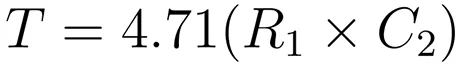
Now, to get frequency by taking the inverse of times period as (1/T), we can change the value of the capacitor and the resistor, but it is recommended to use the value that components are available; therefore, choose capacitance as 4.7µF and resistance as 1KΩ. It gives a frequency of 47Hz, which would be enough for simple loads. If you want to get the exact frequency, you need to select the resistance accurately.
The chip generates the clock pulses, which are taken to the N-MOSFET to drive the transformer. The transformer steps up the 12V to 230V. So every time a pulse reaches the MOSFET gate, we will have a 220V half cycle at the output. In the next pulse, the second MOSFET triggers the second half cycle of 220V. So, with two MOSFETs turning on and off at 50Hz frequency, we will have a 50Hz 220V cycle output at the transformer end.
After the MOSFETs, the low-voltage current is dealt with by a step-up center-tapped 12-0-12 transformer to make the voltage 220 volts.
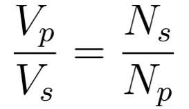
The above formula will be used for the secondary voltage of the transformer with the number of turns in the primary and secondary coil. Connect the two wires from the drain pin of the MOSFETs to the two extreme wires of the transformer, and the center wire of the transformer will be connected to the Vcc, the battery-positive terminal.
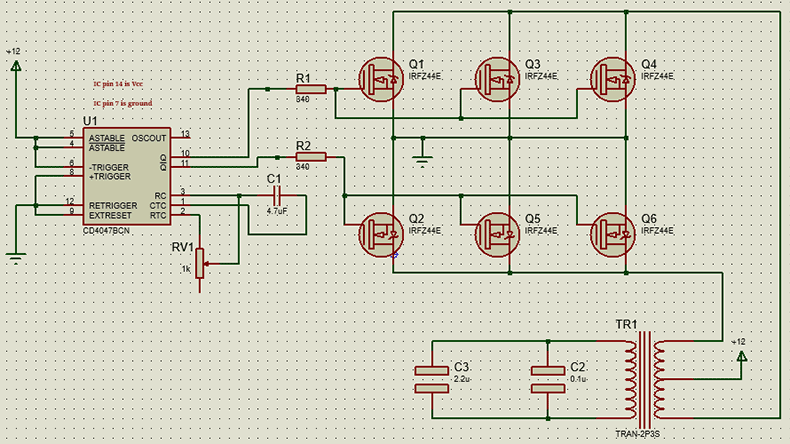
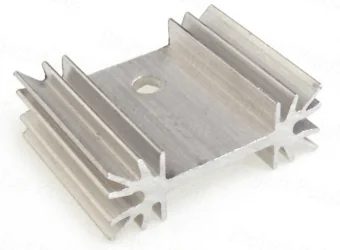
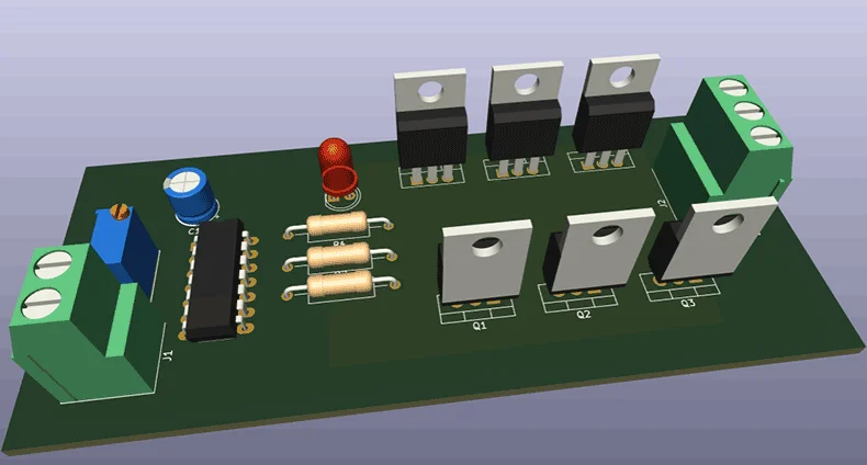
On the output side, use the decoupling capacitors after the transformer. The MOSFETs IRFZ44n will heat up, so use heat sinks to minimize this. Use heat sinks with all MOSFETs.
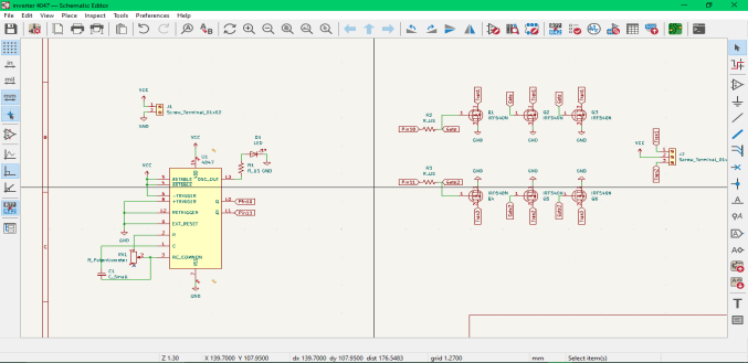
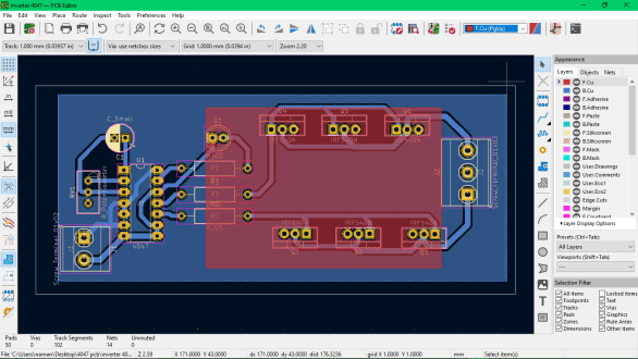
The PCB of the circuit is designed in the KiCAD 7.0 software.
|
CD4047
|
--
|
x1
|
|
Resistor
|
330Ω
|
x3
|
|
IRFZ44n
|
--
|
x6
|
|
T-Block
|
2 screw
|
x1
|
|
T-Block
|
3 screw
|
x2
|
|
Potentiometer
|
1kΩ
|
x1
|
|
LED
|
--
|
x1
|
|
Heat Sink
|
--
|
x6
|
This inverter will run appliances such as AC LED bulbs and incandescent bulbs. The LED bulb has low power dissipation, so its intensity will not be affected. However, the latter will rum dim. The system's output wattage will be 60W. Therefore, appliances below this watt will run. If a fan is operated on it, then it will produce noise because it is not a pure sine wave.
One problem faced is the temperature of the MOSFETs. Use proper heat sinks with the MOSFETs.
Inverter with transistors
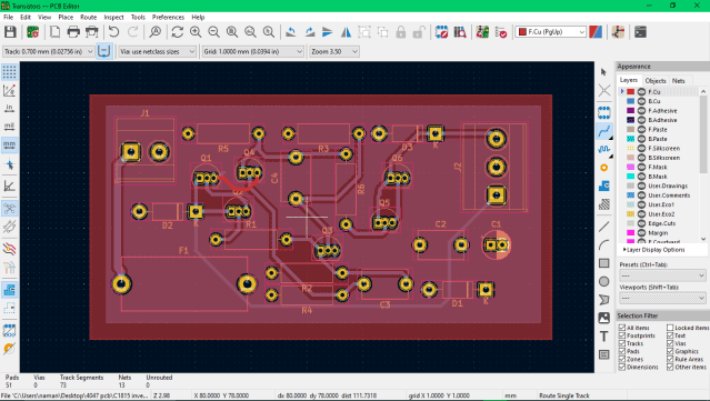
The schematic and the PCB layout are designed in KiCAD 7 software.
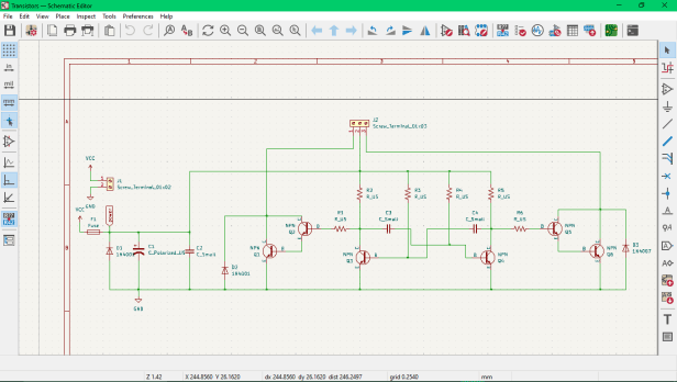
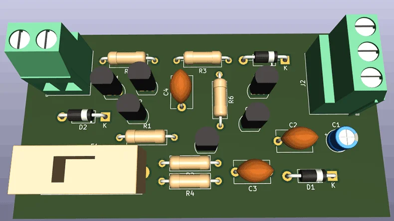
The main component of this circuit is transistor C1815, an NPN transistor. The combination of the transistors, as shown in the figure, gives two clock pulses with a 180-degree phase change.
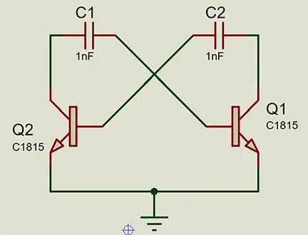
The duty cycle of the pulses can be changed by changing the value of capacitors and resistors. This type of inverter can be efficient in a manner that there is no heating issue. Also, the waveform passes through the amplifying transistors; therefore, the voltage at the transformer ends is sufficient. But this type of inverter circuit has a lot of noise as in the amplification of the waveform in the amplifier transistors the noise or disturbance is generated. It requires a lot of decoupling capacitors and filters, which will minimize the noise.
In all the inverter circuits explained, either the voltage level is very low or there is a noise that can affect the performance of the appliances. Therefore, it is not safe to operate appliances such as refrigerators, microwave ovens, air conditioners, etc. But appliances such as bulbs and soldering iron lamps can be run. For a high efficiency for some appliances, the suitable method is to use the micro-controller for feedback. In this way, the feedback ensures the quality of the waveform and the voltage as well. The price of a microcontroller such as Atmega 8051 is affordable. By the usage of PWM, the efficiency of the inverter can be improved.
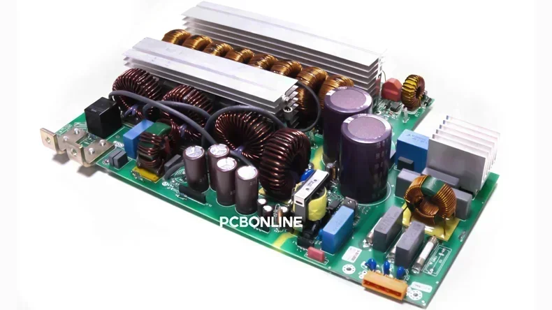
PCB Assembly for Industrial Inverter Boards
High-power industrial inverter boards require high solder fullness, tin intake, and overall heat dissipation of the system. In the printed circuit board (PCB) fabrication and assembly process, the large area of through-hole technology (PTH) assembly makes it difficult for the PCB assembly manufacturer to bring out the electronics manufacturing.
The PCB assembly manufacturer PCBONLINE has rich production experience in PCBA manufacturing for industrial inverters. We take care of details such as jig design, reflow oven temperature control, and production process design, which is why we can produce such high-power, high-current boards.
PCBONLINE is an advanced PCB manufacturer and assembler to meet all your industrial inverter boards' requirements.
Apart from industrial inverters, PCBONLINE has rich inverter manufacturing experience for EV, PV, and consumer devices.
Founded in 1999, PCBONLINE has two large advanced PCB manufacturing bases, one PCB assembly factory, and an R&D team to provide you with one-stop electronics manufacturing.
Relying on the EMS PCB assembly factory, PCBONLINE can source inverter board components like MOSFETC, IGBTs, capacitors, inductors, Microcontrollers, diodes, etc, at very affordable costs.
High-quality PCBA manufacturing certified with ISO 9001:2015, IATF 16949, RoHS, REACH, UL, and IPC-A-610 Class 2/3.
Besides PCB fabrication and assembly, PCBONLINE also provides box build assembly for inverter applications.
Suppose you need any inverter boards, such as industrial inverters, EV inverters, solar inverters, etc. In that case, you can ask PCBONLINE to work for your boards, including R&D, PCB fabrication, component sourcing, PCB assembly, and box-build assembly. If you need converter boards, such as EV charging piles, PCBONLINE can also meet your demands. To send your inquiry, please get in touch with PCBONLINE by email at info@pcbonline.com.
Conclusion
Inverters transform AC into DC so that home appliances, EV motors, industrial equipment, etc., can be powered by lithium-ion batteries, solar PV batteries, and grid-connected PV power. To pave your basics to design inverter board, we introduced three basic inverter circuits. For advanced applications, Microcontrollers should be used in the inverter circuit. To bring your inverter board design to life, don't hesitate to work with the one-stop PCBA manufacturer PCBONLINE./p>
PCB assembly at PCBONLINE.pdf


