
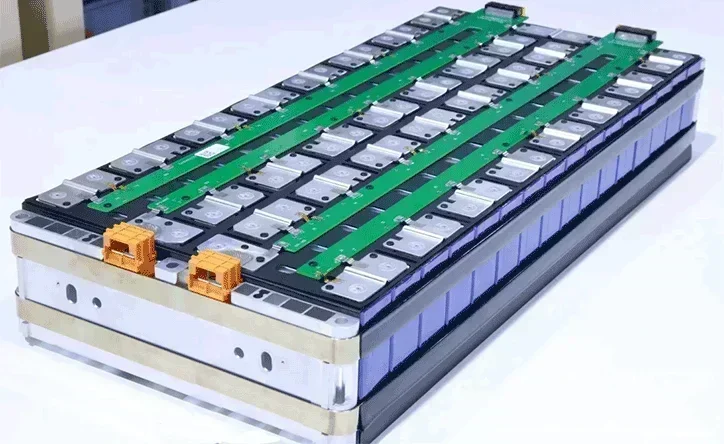
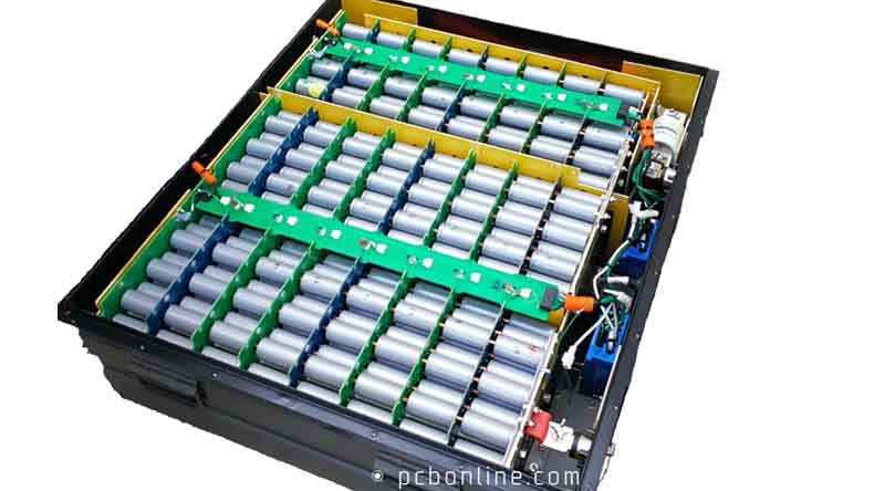
Lithium battery packs are the power source for electric vehicles (EVs) and hybrid electric vehicles (HEVs). In a lithium battery pack, the cell contact system is the electrical connection module that connects the battery cells and the BMS (battery management system).
This article comprehensively introduces battery cell contact systems (CCS), including the CCS functions, components, CCS types, manufacturing process, design, what to provide for the R&D of the CCS module, and the CCS module one-stop manufacturer PCBONLINE.
In this article:
Functions of a Battery Cell Contact System Components of a Battery Cell Contact System Types of Battery Cell Contact System FCP Assembly for the Battery Cell Contact System One-Stop Battery Cell Contact System Manufacturer PCBONLINEFunctions of a Battery Cell Contact System
A cell contact system, also called a cell contacting system, is custom-designed according to the series and parallel connection of the lithium-ion battery cells. It replaces the numerous wiring cables and thus saves much space in the lithium-ion battery pack. It is thermally laminated or blister tray riveted.
The functions of an EV battery cell contact system are:
Circuit connection
In an EV battery pack, the CCS connects the battery management system (BMS) and the lithium battery cells electrically and electronically.
The CCS module's copper busbars connect the lithium battery cells by laser welding to achieve high-voltage connections.
On a CCS, there is at least one connector. When the CCS module is delivered to the EV battery pack manufacturer, they can connect the BMS and the CCS.
Besides, the CCS is placed on, above, or between the battery cells and is also connected to the BMS, connecting the cells and BMS.
Temperature monitoring and protection
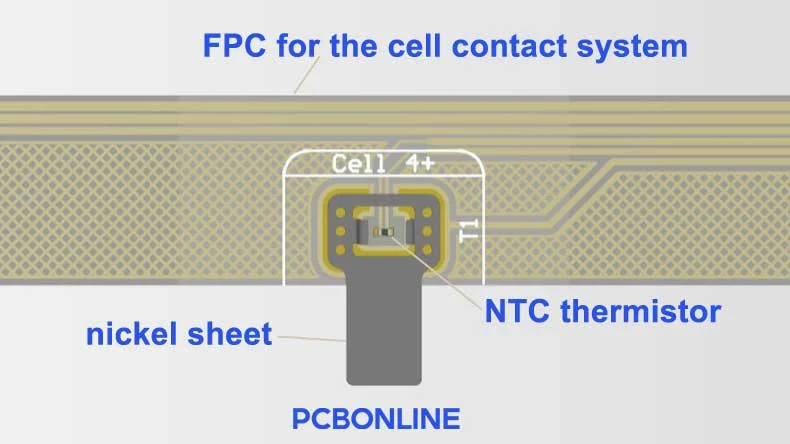
In a CCS, there are many NTC (negative temperature coefficient) thermistors whose resistance changes non-linearly according to the temperature changes. They are surface mounted on the PCB or flexible PCB.
An NTC is placed near the nickel sheet, which is laser-soldered with a copper busbar connected to the cells. Thus, the temperature changes of the cells are directly reflected by the resistance changes of the NTC.
Through the NTC thermistors, the CCS module collects the temperature changes in the battery cells and transfers them to the BMS. The BMS can then analyze and control the batterycells' status.
EV fast and slow charging
Besides circuit circuit connection and temperature monitoring, the CCS is the pathway for fast and slow charging of EVs and HEVs.
When the battery power is relatively low, charging is in fast charging mode. When the power reaches about 98%, it is slow charging. It is similar to the situation of smartphones.
In the fast charging mode, the high currents flow through the copper busbars to the cells. When it comes to slow charging, the small currents flow through the circuit traces on the PCBA or flex PCBA of the CCS to the battery cells.
How does a CCS work to achieve these functions? Learn about the structures of a battery cell contact system to know how.
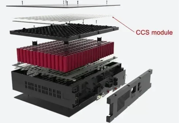
Structures of a Battery Cell Contact System
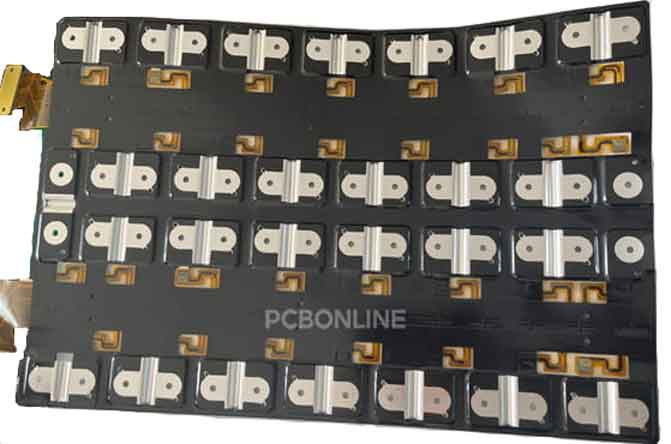
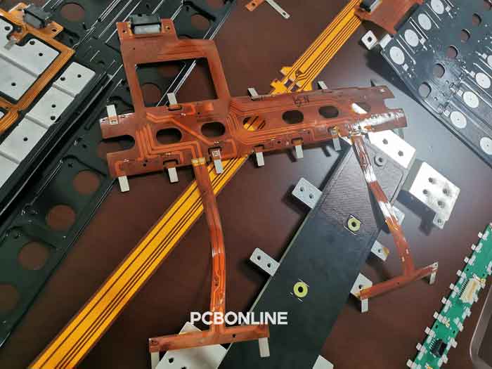
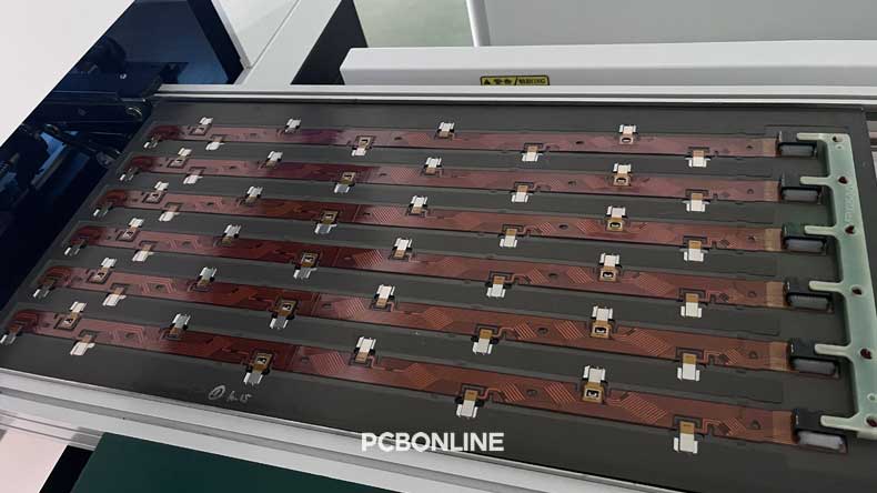
A battery cell contact system is composed of a signal collect PCBA (FPC, RF4 PCB, FDC, FFC, or wiring cables), two or one piece of insulation films on the top and/or bottom, and copper busbars.
Currently, the flexible printed circuits CCS is the most common battery cell contact system for an EV's lithium battery pack.
The FPC assembly of a battery CCS is surface-mounted with SMDs (surface-mounted devices). Its SMDs include connectors, NTC thermistors, and nickel sheets.
Insulation film
The insulation films of the CCS insulate between the battery cells and the battery pack's aluminum enclosure from the shorts.
It is a PET (polyester) black or yellow insulation film. If CCS has two films, the FPC PCBA is sandwiched between the insulation film and thermally laminated. If the CCS has one film, the flexible PBCA is thermally riveted with the insulation film by blister trays.
Busbar
A CCS module has multiple copper busbars according to the different layouts of the battery cells.
Generally, the material for the busbar is copper. But it can also be aluminum or copper plated with nickel. The material of the battery cell's electrode pole decides the busbar material.
If the battery cell's pole is pure nickel, we use aluminum busbars in the battery cell contact system.
If the battery cell's pole is copper, we use copper busbars in the battery cell contact system.
In the copper busbars, there are holes drilled for laser soldering with the positive and negative electrodes of the battery units. (Note: Laser soldering to connect the busbars and the electrodes of the cells does not happen during the cell contact system assembly. After the CCS assembly, the battery pack system manufacturer laser solders the busbars, cells, and enclosure.)
Copper busbars achieve the connection of the battery cells in series and parallel circuits.
In a battery cell contact system, a copper busbar connects with a nickel sheet of the CCS module so that the CCS module can detect the temperature changes of the battery cells.
PCBA
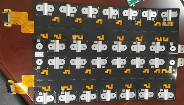
The most popular types of CCS modules use FR4 PCB or flexible PCB. On the PCBA (printed circuit board assembly), there are surface-mounted NTCs, nickel sheets, and connectors.
NTCAn NTC thermistor is a resistor whose resistance gets smaller as the temperature increases. It is used as a temperature sensor on the battery cell contact system to detect temperature changes.
On the FPC for the CCS, the NTC thermistors are surface mounted in the hollow areas of the nickel sheet.
Here's how the battery CCS monitors the temperature changes of the battery cells:
The BMS emits an electric current to the NTC, and the current goes through the NTC and back to the BMS. As the temperature changes, the current changes, and the BMS can analyze the temperature changes of the lithium-ion battery cells and control the status of the battery pack.
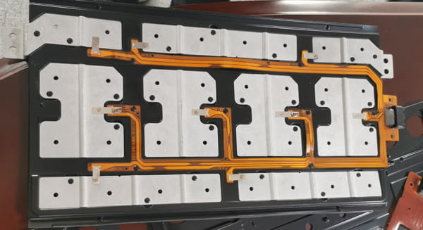
From the below FPC PCBA, you can see the nickel sheets but can't see the NTC thermistors, this is because in the assembly process, the PCBA manufacturer doses glue in the hollows of the nickel sheets to tightly fix the nickel sheet on the FPC.
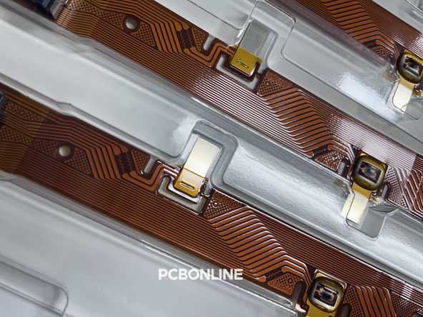
Nickel sheets are custom-made for the cell contact system. One end with a hollow is surface mounted on the FPC and dosed with glue in the flexible PCB assembly process.
When we further assemble the PCBA with busbars and plastic films to be the battery cell contact system, we laser solder or rivet with a screw to connect the other end of the nickel sheet to the busbar.
The battery cell contact system manufacturer manufactures and assembles the flexible PCBA for the CCS, and also manufactures the nickel sheets and busbars for it. You can watch a short video below of nickel sheet manufacturing for the CCS module.
Connector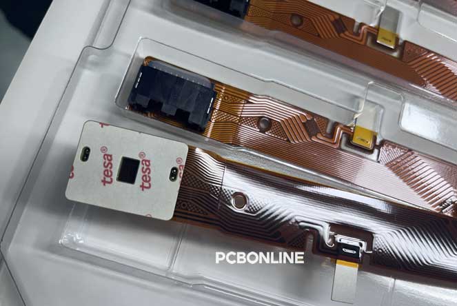
At the ends of the FPC for the battery cell contact system, there are connectors. They are surface-mounted on the FPC. They are used for connection between the CCS and the BMS.
FPCA CCS using FPC has the most mature technology. As FPC costs go down, the fabrication of this type of CCS is becoming affordable.
In a battery cell contact system, the FPC, or flexible PCB, is PI (polyimide) based. It uses adhesive and rolled annealed copper as the CCS is in static uses.
Besides, the FPC used in a CCS is usually single-layer.
In the flexible PCB manufacturing process, toll-to-toll copper foil is preferred as the toll-to-toll process has a higher yield rate and the flex PCBs have a consistent dimension tolerance and a stabler performance.
The cell contact system manufacturer PCBONLINE uses the toll-to-toll method in flexible PCB manufacturing. The length of the flexible copper foil has no maximum limit, and the maximum width is 250mm.
Types of Battery Cell Contact System
Battery cell contact systems have developed into the FPC CCS from several stages. The types of cell contact systems, include wiring cables + components, FFC (flexible flat cable) + components, FR4 PCBA, FDC (flexible die-cutting) + components, and FPC PCBA.
Below we list their pros and cons and briefly introduce them and their manufacturing process.
Wiring cable CCS
Pros: Provide the earliest solution for the lithium battery pack and start the development of the CCS module
Cons: heavy, take up too much space, low automation of the cell contact system manufacturing process
The earliest battery cell contact system uses wiring cables to connect between the lithium-ion battery cells and between the busbars, components, and the BMS.
The multiple wiring cables take up too much space in the lithium battery pack, especially the connection among the battery cells.
Besides, the assembly requires technicians to manually fix the terminals.
As the battery pack gets smaller, and electronic manufacturing gets more automatic, the wiring cable CCS solution is eliminated for EVs and HEVs nowadays. Wiring cables are still used in the battery pack of electric bicycles without a CCS.
FFC (flexible flat cable) CCS
Pros: lighter, smaller size than the wiring cable solution, automatic production
Cons: Not reliable enough for automotive vehicles' battery packs, still stake up much space
An FFC is made from an extremely thin and fine tin-plated flat copper wire that is hot-pressed to bond an insulating PET-based coating. The hot press process is automated.
The FFC solution was developed after the wiring cable solution. The flexible flat cables work the same as the wiring cables to connect the battery cells, busbars, components, and the BMS. Compared to the wiring cables, they are thinner and have a smaller size, and the FFC CCS assembly process is automated.
The manufacturing process of the FFC is: Copper wire rolling → hot bonding and molding → electrical testing → cutting → full inspection.
However, the reliability of the FFC solution is not enough, as the insulating coating has to keep mechanical stability, shear resistance, aging resistance at high temperatures, and cold/thermal shocks. However, it is difficult for the PET coating of so many flexible flat cables to achieve these.
Besides, the space and weight of the many flexible flat cables are smaller than the wiring cable solution but still too large for a battery pack.
FR4 PCB CCS
Pros: lighter than wiring cable and FFC solutions, greatly reducing the CCS size and quantity of cables
Cons: rigidity, still take up much space
FR4 PCB is rigid PCB. It can integrate the circuit traces and connect the nickel sheets, connectors, and the BMS.
FR4 PCB integrates the circuits so that the quantity of wiring cables is reduced a lot. However, FR4 PCB is rigid, wiring cables are still needed in the FR4 PCB CCS module to connect the BMS, busbars, and the other FR4 PCB cell contact systems.
What's more, the weight and size of FR4 PCB are much larger than FPC.
FDC (flexible die-cutting circuit) CCS
Pros: Small space, automatic production, fewer steps in the manufacturing process, lower price
Cons: the FDC CCS technology is not mature enough, the circuit has to be very simple on the FDC
An FDC is a PI-based die-cutting circuit. Its circuit, between two insulation films, is single-layer and flexible.
On the FDC, there are also pads for welding. The welding method is very different from PCB component soldering. The components are soldered on a plate board, and the pads of the FDC are laser welded with the contacts of the plate board.
The manufacturing process of the FDC is: Die cutting → thermal lamination → SMT. However, its circuit has to be much simpler than the FPC. The circuit width and space have to be large enough, and there's only one single-sided on the circuit.
Furthermore, the cell contact system has precision requirements for the circuits. In such a case, die-cutting to create circuits on a flexible copper-clad laminate is difficult.
FPC (flexible printed circuit) CCS
Pros: Mature CCS technology, precision, fine-pitch, reliability, high performance, automatic production, stable signals, uniform dimension
Cons: Many steps in the FPC manufacturing process
As we've mentioned in the first part of this article, an FPC for the CCS is a flexible printed circuit board that has 1 to 4 layers. Its circuit can be fine-pitch. In the flexible PCB manufacturing process, the CCS manufacturer uses the toll-to-toll foil to ensure the best performance of the FPC.
The FPC battery cell contact system manufacturing process is: FPC manufacturing → nickel sheet manufacturing → SMT assembly of mounting NTC thermistors and nickel sheets on the FPC → attach insulation films → dosing glue in the hollow of the nickel sheet to tightly fix the nickel sheet to the FPC → laser soldering the other end of the nickel sheet to the busbar → thermal lamination or riveting with blister trays.
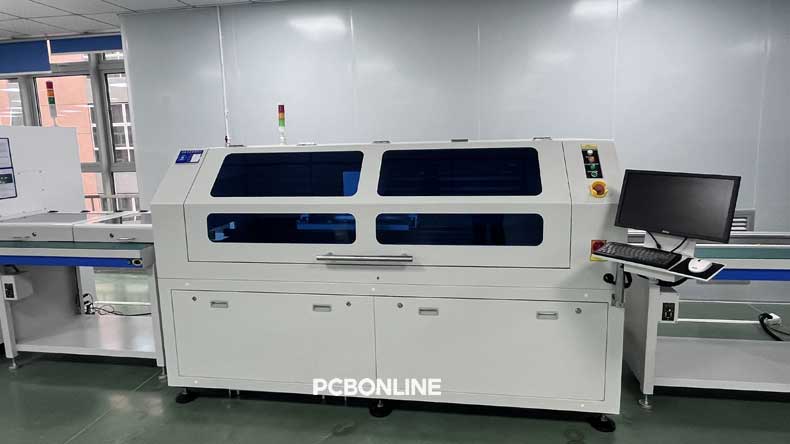
At the one-stop CCS manufacturer PCBONLINE, the detailed process of SMT assembly for the FPC of the CCS is below.
FFP Assembly for the Battery Cell Contact System
Step 1. Put an FPC on a jig
In flexible PCB assembly, the FPC is put and fixed on a jig so that it can be surfaced mounted without any moves or offset.
Step 2. Solder paste printing
The FPC on the jig is automatically sent into the solder paste printing machine, where the solder paste is silk screen printed on the pads of the FPC.
Step 3. 3D SPI
Three-dimensional solder paste inspection is necessary for CCS FPC. It ensures the solder paste is qualified for soldering the SMDs to the FPC.
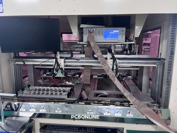
Step 4. Picking and placing components on the FPC
This step only needs one mounting machine, as the SMDs on the FPC are in small quantities, including the NTC thermistors, nickel sheets, and connectors.
In the FPC assembly for the battery contact system, the component mounting machine is in a small size, and the feeders that send components into the mounting machine are also in a small quantity.
Step 5. Reflow soldering
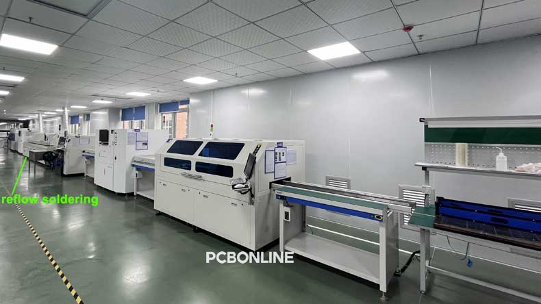
The PCB mounted with SMDs is automatically sent into the reflow soldering oven to reheat and bake until the solder joints form the metallic compound. This marks the PCBA soldering success. Then the FPC PCBA is cooled down and goes out of the oven.
Step 6. 3D AOI (automatic optical inspection)
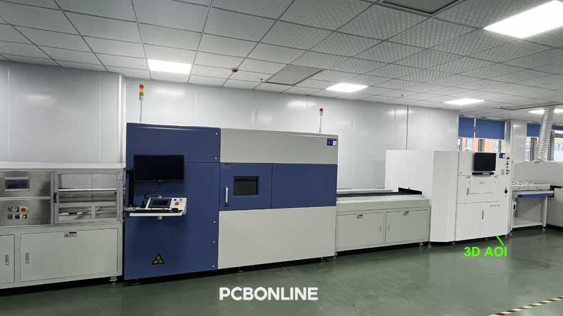
We use 3D AOI to ensure the quality of the component soldering.
Why is the AOI for FPC assembly for the battery cell contact system three-dimensional? Because the solder has to "climb" to about 0.2mm on the NTC thermistor for the circuit connection quality.
Reliability is important because the battery cell contact system will be sealed in the lithium battery pack for automotive vehicles. It is almost impossible to take out the FPC PCBA once it is thermally laminated with the insulation films and the busbars. We need to inspect all surfaces of the solder joints with the 3D AOI.
Step 7. 3D X-ray inspection
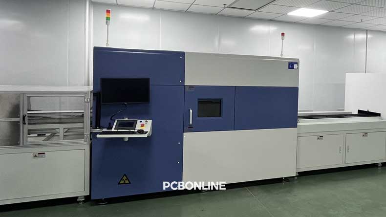
Why is there a 3D X-ray inspection? The reason is the same, to ensure the FPC PCBA quality.
As we mentioned, the NTC thermistors are placed in the hollow of the nickel sheet. Some solder areas between the NTC and the nickel sheet are inevitably blocked and the AOI cannot capture the picture. So we use the 3D X-ray machine to inspect the PCBA.
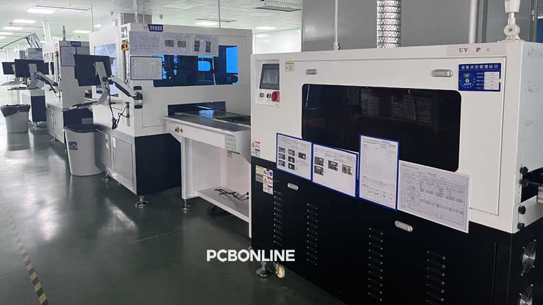
What's more, the 3D X-ray machine is set on the SMT line permanently, not detachable. So is the above AOI machine. The entire PCBA production line is specially for the FPC assembly for the battery contact system.
Step 8. Labeling the not-good PCBA
The automatic labeling machine follows the 3D X-ray on the production line. It labels the PCBA so that there is no human intervention on the flexible PCBA for the CCS.
The not-good PCBA will be repaired and separated from the good ones permanently since labeling.
Step 9. Visual inspection
Quality control members at PCBONLINE will visually check the flexible PCBA for the battery contact system.
Step 10. Attach a film on the FPC and the nickel sheets
Here a film is automatically attached to the FPC and the nickel sheets. The film, generally transparent or half-transparent, is made of PI or PET. It prevents damage to the nickel sheets and the FPC from the external environment and provides additional mechanical strength to the FPC.
Step 11. Plasma cleaning of the FPC PCBA
We use the Plasma to clean the flexible PCBA of the battery contact system. For automotive-grade PCBA used in the battery pack, no dirt or contamination is allowed.
Step 12. Dosing glue
At the step, the glue is automatically dosed in the hollow of the nickel sheet, where the NTC thermistor is placed.
The aim of dosing glue is to further fix the nickel sheet to the FPC. We use glue to dose because laser can't be used here.
Step 13. UV baking the glue
The PCBA is under the UV light. This is to bake the glue to cure.
Step 14. ICT testing
Now is ICT or in-circuit testing the PCBA to ensure the circuits of the entire flexible PCBA are hassle-free.
Step 15. QR code printing
At the end of the flexible PCBA for the battery cell contact system, we print the QR code on the FPC assemblies so that they are traceable. The users or battery pack manufacturers can scan the code to know all the details of the FPC PCBA and materials' origins.
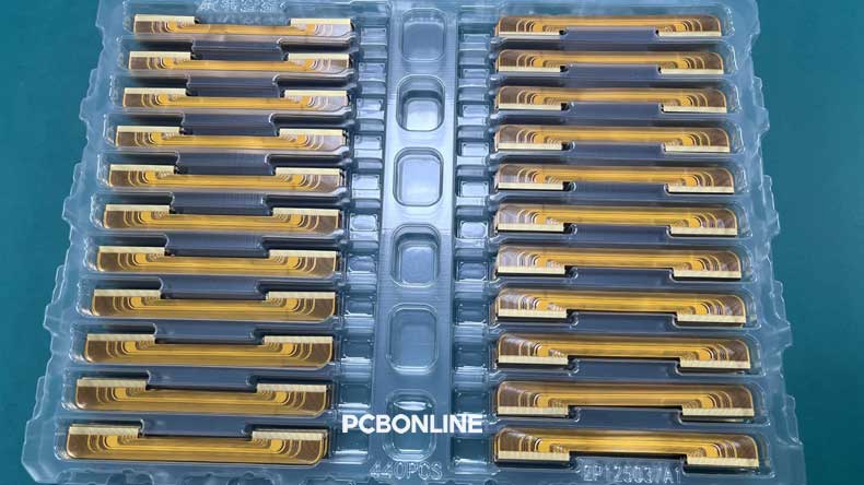
The FPC assembly is finished now. Next, the FPC assemblies are placed on a jig.
Then the PCBA is thermally laminated with black insulation films and the busbars and becomes the battery cell contact system by lamination or blister tray.
Though the quantity of SMDs on the FPC is small, and the structure of the battery contact system seems straightforward, the design and manufacturing of the CCS module have strict quality and performance requirements, especially in thermal dissipation, material selection for different components of the CCS, the toll-to-toll foil, the maximum length and width of the FPC, the sides of the battery cell electrodes in the design, etc.
Suppose you need reliable and affordable battery cell contact system manufacturing for electric vehicles, hybrid electric vehicles, or energy storage applications. In that case, you can work with a one-stop cell contact system manufacturer PCBONLINE.
If you need a CCS design, you can also contact PCBONLINE and provide the requirements so that it can be designed as expected. What to provide for the R&D of the battery cell contact system is also listed below.
One-Stop Battery Cell Contact System Manufacturer PCBONLINE
PCBONLINE is a one-stop battery cell contact system manufacturer providing CCS manufacturing and design.
Founded in 1999, PCBONLINE has two large advanced PCB manufacturing bases and one PCB assembly factory. We can fabricate and assemble the FR4 PCB and FPC for the battery cell contact system and further laminate them into the CCS modules.
In the CCS design, we suggest designing the battery cells' anodes and cathodes to be on one side and so is the other side. This is because the cell connection can be easier. We can also design all the anodes and cathodes on the same side. It is not suggested to design all the cells' anodes on one side and all the cathodes on the other side, because such design takes up space to connect the cells.
The maximum length of CCS is 2.2m, the maximum width is 1m, and the thickness depends on the currents you plan to flow through
PCBONLINE can fabricate and assemble the FPC or FR4 PCB for the battery cell contact system and further assemble the PCBA to be a cell contact system.
Besides the FPC and FR4 PCB for the CCS, PCBONLINE custom fabricates the nickel sheets.
PCBONLINE has a professional R&D team that can design the entire battery contact system and provide design assistance to you.
Special production line for CCS manufacturing, including 3D SPI, 3D AOI, 3D X-ray, the Plasma process, etc.
PCBONLINE offers free samples and R&D for bulky production (When the project goes to the bulky production stage, the prototype and R&D fees are returned).
CCS manufacturing is certified with RoHS, IATF 16949, ISO 9001:2915, REACH, UL, and IPC.
Here is a table of data needed to provide to PCBONLINE for the design of your battery cell contact system:
What to Provide to PCBONLINE for CCS Design
|
CCS module outer dimension data
|
Product performance requirements
|
|
Cell pole & top cover structure matched with the CCS
|
CCS operating current (It determines the material and thickness of the connecting busbars)
|
|
Positioning of the plastic bracket
|
CCS electrical performance requirements (related to material selection)
|
|
Insulation structure of the outputs
|
Number of series and parallel connections
|
|
Size of the outer dimension
|
Cell voltage definition and circuit definition, special requirements, etc.
|
|
Battery cell's laser welding area and laser welding thickness
|
/
|
So far, PCBONLINE has designed and manufactured different battery cell contact systems for electric cars and electric motorcycles for OEMs from Europe, India, Korea, etc. If you need CCS module manufacturing or design, contact PCBONLINE at info@pcbonline.com.
Conclusion
This article comprehensively guides you through what a battery cell contact system is. FPC is the most used CCS module due to the flexible and fine circuits, lightweight, thin thickness, small size, uniform dimension, stable signal, high reliability, and mature technology. The one-stop CCS manufacturer PCBONLINE not only provides FR4 PCB and FPC cell contact system manufacturing but also provides R&D of the CCS module. You can contact PCBONLINE by email or communicate with us from the online chat window.
Battery Management System Manufacturing at PCBONLINE.pdf
CCS Product Introduction - PCBONLINE.pdf


