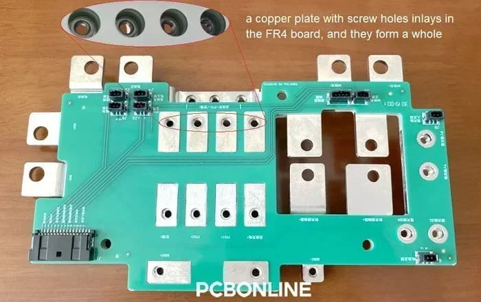
A busbar (sometimes spelled bus bar) is a metallic strip or bar. Most busbars are made out of brass or copper.
In most cases, busbars do not contain insulation, but their rigidity is adequate to allow them to be held in the air by insulated pillars.
A busbar provides adequate cooling for the conductors, and it is possible to tap in at various sites without creating a new joint.
For these qualities, busbars are soldered, inlaid, or embedded in PCBs (printed circuit boards) and used in other parts of electronic systems in the field of electric power distribution.
This blog gives an introduction to PCB busbars, including their types and how to design busbars in a PCB.
Part 1. What is PCB Busbar
A PCB busbar can perform electrical conductivity between circuit boards, electronic components, power units, and battery banks.
In the realm of advanced electronics and circuitry, PCB busbars are specifically designed onto printed circuit boards as a solution to various challenges, such as electrical and thermal conductivity, and mechanical support and connection.
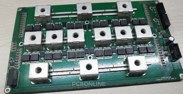
Compared with copper traces, PCB busbars have a larger thickness and width, so they can withstand a high current and voltage.
Besides, a PCB busbar serves as a support structure, as it is rigid and rugged.
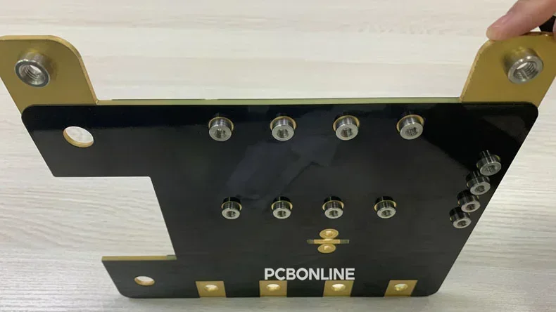
What's more, PCB busbars can act as a mechanical connector to the PCB, as it can install screws and other metal parts for connection with the other PCB or the system.
PCBs equipped with busbars are used in a wide variety of fields, ranging from high-power electronics to precise instrumentation.
Busbars are often placed within switchgear, panel boards, and busway enclosures for local high-current power distribution.
Additionally, high-voltage equipment in electrical switchyards and battery banks are connected with busbars.
Part 2. PCB Busbar vs. PCB Stiffener
When you think about PCB busbars, you probably have heard about PCB stiffeners.
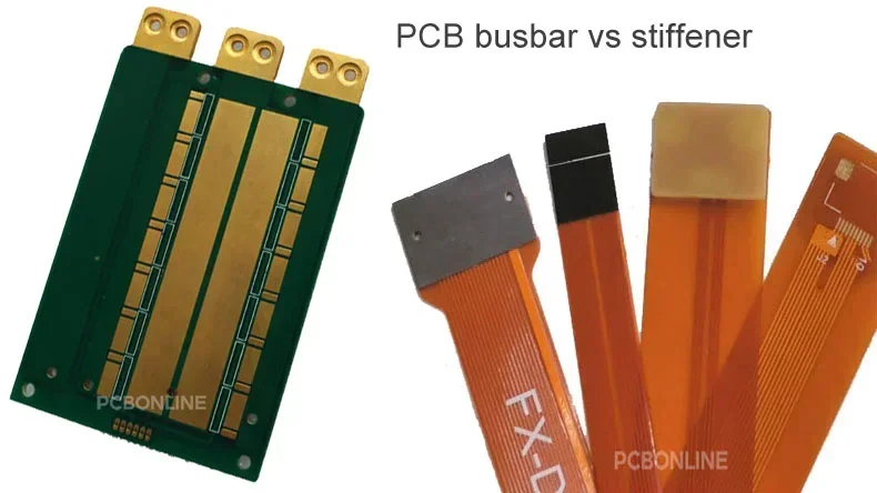
Both serve structural support and mechanical connection to the PCB.
However, PCB busbars and stiffeners are different in many aspects.
PCB busbars can be used in any type of PCB as long as they meet the EMC (electromagnetic compatibility) requirements. While PCB stiffeners are used only in flexible PCBs.
PCB busbars can conduct electricity, while stiffeners can't be used for electricity connection.
PCB busbars are soldered, inlaid, or embedded in the PCB, while stiffeners are attached to the flexible PCB.
At the advanced PCB manufacturer PCBONLINE, both busbars or stiffeners can be designed and fabricated on PCBs.
Part 3. Types of Busbar on PCB
What types of PCB busbars can you design on a PCB? Check them below.
Copper PCB Busbars
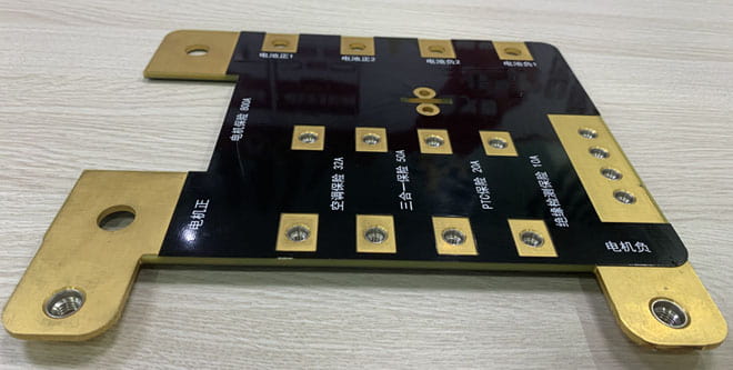
Copper has a low heat resistance and a low electrical resistance, and it also has a high mechanical strength. These features make copper busbars highly adaptable.
In high-current PCB designs, copper busbars and terminal blocks are typically used for large-current conductivity.
Additionally, a copper busbar has excellent resistance against wear and strain.
Copper busbars are used in high electrical conductivity applications, such as busway enclosures and switchgear to distribute large levels of electrical current.
Aluminum Busbar
Aluminum PCB busbars have a lower conductivity than copper, yet they are still able to withstand moderate to high currents.
Aluminum is cheaper and lighter than copper in the same thickness and size.
Because of the low weight and low cost, aluminum busbars are appropriate for electricity distribution in situations where weight and cost considerations are present.
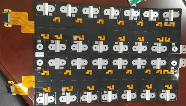
For example, aluminum busbars can be used in the CCS (cell contact system) assembly of lithium battery packs for electric vehicles.
Flexible Busbar
Compared to conventional rigid busbars, flexible busbars can bend and twist without losing their ability to retain electrical contact.
Flexible PCB busbars are manufactured by laminating numerous layers of conductive material with layers of insulating material.
Flexible busbars are used in situations where movement, bending, or vibration is anticipated.
Multi-layer busbars
PCB busbars that have many layers are referred to as multi-layer busbars.
Multilayer busbars are manufactured by stacking numerous layers of conductive traces and insulating materials.
They are used in intricate multilayer PCB designs to facilitate the effective distribution of power and signals across the many layers of the PCB.
Part 4. Pros and Cons of Busbar in PCBs
Before you employ busbars on PCBs, this article sheds some light on the potential benefits and drawbacks of using PCB busbars.
Advantages of PCB Busbar
Enhanced Rigidity and Strength: By using busbars and stiffeners, PCBs have structural integrity significantly improved. Enhanced strength helps PCBs survive in challenging situations.
Power Distribution Optimization: Busbars provide a reliable foundation for the effective distribution of power. In power-sensitive applications, it is essential to keep the power supply constant. PCB busbars make it possible for power and ground circuits to carry more current and maintain a stable power supply.
Thermal Dissipation Optimization: PCB busbars improve the thermal dissipation of the PCB components and the entire electronic products. Using PCB busbars can protect thermal-sensitive components from overheating.
Mechanical connection: It is common that busbars have screw nuts or holes. The screw nuts or holes of the PCB busbar enable the PCB to fix or connect with other parts by screws or terminal blocks.
Disadvantages of PCB Busbar
Increased Manufacturing Complexity: When busbars are integrated into a product, the manufacturing process might become more complicated, which could result in higher production costs.
Design Constraints: Busbars may impose limits on the architecture of the PCB and the positioning of components, which calls for careful design considerations.
Assembly Challenges: The inclusion of busbars may make the PCB assembly difficult, as the busbar conducts heat quickly so higher reflow temperatures are required. In PCBA manufacturing, engineers should pay attention to guarantee the components are integrated without being damaged.
EMI (Electromagnetic interference)/EMC Considerations: In a busbar PCB design, it is essential to reduce coupling around the PCB busbar. The signal traces should stay away from the high-voltage busbar and avoid paralleling with it. Using busbars makes PCB design more difficult.
Part 5: Considerations of Designing PCB Busbar
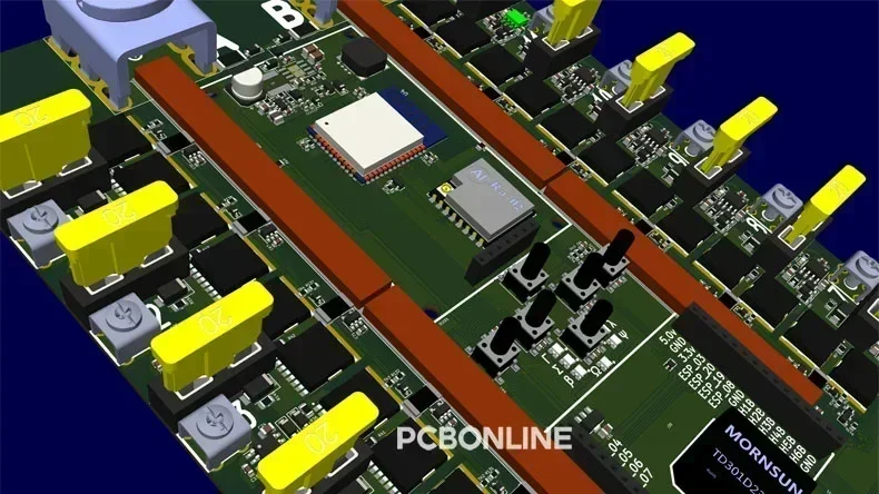
It is necessary to design a busbar PCB that is free of breaks, damage, and malfunctions.
When designing a PCB with busbars, a comprehensive approach is required.
A careful balance between electrical performance, thermal management, electromagnetic compatibility, and other factors should be taken into consideration.
EMI control
To reduce the impact of EMI, a number of different grounding, shielding, and signal isolation strategies are used.
The positioning of components, the choice of dielectric material, and the regulated impedance routing are all factors that contribute to the reduction of signal degradation and cross-talk.
To predict EMI problems and ensure the signal's integrity, you need to have simulation tools.
To reduce the effects of electromagnetic interference, EMC procedures such as grounding and shielding are necessary.
The end goal is to lower the probability of electromagnetic radiation.
The robustness of the design to interference may be ensured by adhering to EMC standards, which also helps to promote stable operation.
Copper Amount
To manage copper use effectively, optimizing trace widths to handle current while limiting overheating and voltage loss is required.
Additionally, copper pours that are planned strategically and have a balanced distribution throughout the various layers contribute to efficient heat dissipation.
Busbar Design
The ability of the busbar to transport current is affected by both the form of the busbar and the area of its cross-section.
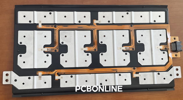
Space limitations must also be taken into account.
Besides, protection against electrostatic discharge, often known as ESD, could be required for exposed busbars.
What's more, the bending radius and the material choice of the PCB busbar must be balanced.
PCB circuits' power distribution, signal integrity, and reliability may all be optimized with a well-designed busbar system by bringing these features into harmony with one another.
Other Factors in Busbar PCB Design
There are other factors for consideration, including:
Thermal management: This calls for the use of methods such as thermal vias and heatsinks.
Performance: To avoid a decline in performance, it is necessary to keep the voltage drop and impedance to a minimum.
DFM (design for manufacturing): The complexity of the design might influence the manufacturing feasibility. Therefore, manufacturability and cost-effectiveness are important considerations.
Compliance: In situations when it is necessary, regulatory compliance guarantees conformity to industry norms.
A well-designed PCB with busbars effectively regulates power, guarantees reliable signal transmission, and reduces EMI problems.
A busbar PCB should retain signal integrity, dissipate thermal energy effectively, reduce EMI, and be reliable when they take into account aspects such as heat dissipation and compliance with regulatory requirements.
If you need one-on-one engineering support or design optimization for your busbar PCB project, you can contact the professional PCB manufacturer PCBONLINE.
Part 6. One-Stop Busbar PCB Manufacturer PCBONLINE
PCBONLINE is a trustworthy PCB manufacturer, providing power and high-current PCB fabrication and high-quality solutions from the initial ideas to the end products.

Founded in 1999, PBONLINE has set up two large advanced PCB manufacturer bases and one PCB assembly factory. It is a private-owned company that is ISO-verified.
PCBONLINE can fabricate any type of PCB with any kind of busbar or stiffener.
PCBONLINE has rich R&D and fabrication experience in thermal management for high-power PCBs.
Besides busbar PCB, PCBONLINE fabricates ceramic PCB, copper-base PCB, and thick-copper PCB for large-current applications.
PCBONLINE provides free DFM, DFT, DFA, and DFX and can optimize your PCB design to reduce costs with quality sacrifice.
Over many years, PCBONLINE has served many busbar PCB projects, such as electric vehicle charging stations, CCS modules for lithium battery packs, air conditioning central systems, etc.
If you need high-quality and affordable busbar PCB, contact PCBONLINE by email at info@pcbonline.com.
Conclusion
To conclude, a PCB not only receives its structural integrity or strength from its busbar, but it also performs the function of an electrical conducting bus. Power distribution, thermal management, and signal integrity are the issues at hand for busbar-integrated PCB designs. Working with PCBONLINE assures that your PCBs are in the skilled hands of professionals and will yield successful results.
PCB Assembly from PCBONLINE.pdf


