
By 2035, the European Union will ban the sales of gas and diesel cars. Electric vehicles (EVs) are the future of automotive. As you know, currently, EVs' power source is the lithium-ion battery pack.
The CCS module, made from a flexible printed circuit board assembly (PCBA) module, is a necessary component of the lithium battery system. This article reveals the whole CCS assembly process for the lithium battery pack, from flexible PCB fabrication, and flexible PCB assembly, to CCS assembly and tests.
Dive to see details of flex PCBA and cell contact system assembly below:
Part 1: CCS Module for Lithium Battery Pack
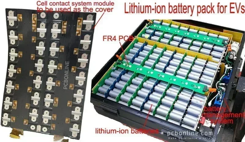
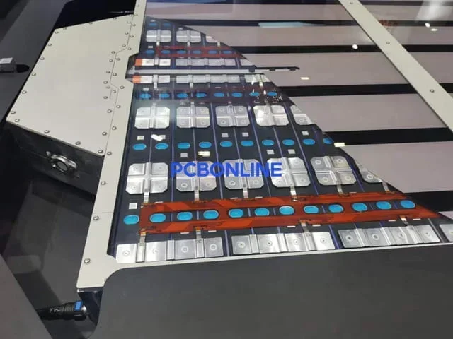
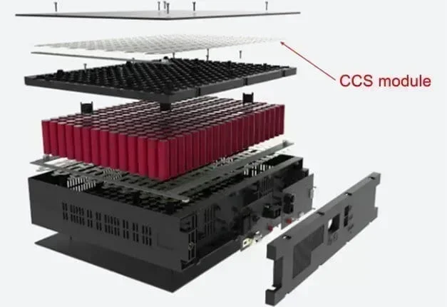
A cell contact system (CCS) module is the cover of the lithium-ion battery pack of EVs.
A CCS module comprises a flexible PCBA module, black films, and nickel sheets. And it is custom-made according to the array of your batteries.
A CCS module collects electric signals from the lithium-ion batteries to drive the EV or from the charging station to the batteries to charge.
In a lithium-ion battery pack, the flexible PCBA embedded in or on the surface of the CCS module collects signals of the lithium batteries and transfers them to the battery management system (BMS) so that the BMS can manage the status of the batteries.
The nickel sheets connect the negative electrode of the power source mounted on the flexible PCB to ground the flexible PCB. This way, the lithium battery avoids electromagnetic interference (EMI) to and from external environments.
Part 2: Cell Contact System Assembly Methods
The cell contact system assembly for lithium-ion batteries is assembling the flex PCBA module, black films, and nickel sheets to be a CCS module. There are two methods of cell contact system assembly: thermal lamination and blister tray processing.
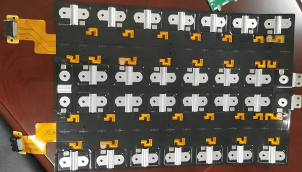
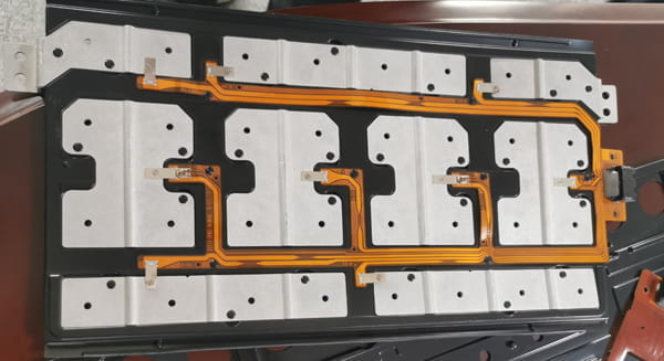
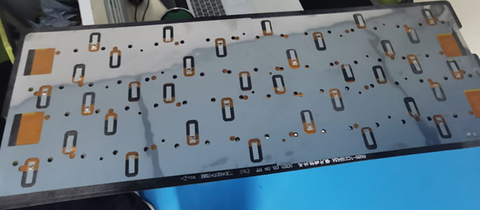
This is a CCS module PCBONLINE fabricated by thermal laminating the flex PCBA, black films, and nickel sheets. The flexible PCBA is embedded in the CCS.
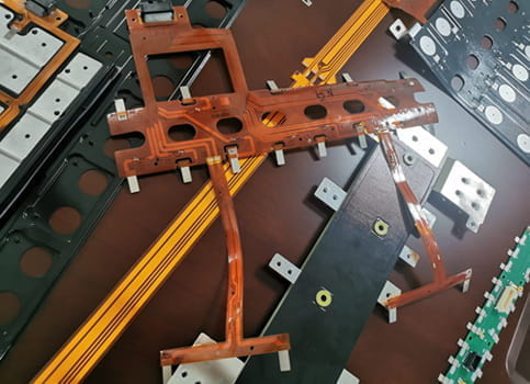
We manufactured the above CCS module by fixing the flex PCBA at the bottom of black films and nickel sheets with screw connecting and blister processing.
Before the cell contact system assembly, we completed flex PCBA manufacturing and nickel sheet mold opening. The cell contact system assembly step is just laminating them to be whole.
As you can see, the most critical process of cell contact system assembly is flex PCBA manufacturing, which is made by surface mounting small nickel sheets and connectors on a flexible printed circuit board and glue dispensing. You can check how we fabricate and test the flexible PCBA in Part 4.
Part 3: One-Stop Flex PCBA and CCS Module Manufacturer
PCBONLINE can fabricate flexible PCB assemblies and further assemble them into cell contact systems for lithium-ion battery packs of EVs. It is a one-stop flexible PCB manufacturer for automotive, medical, industrial, and consumer electronics.
PCBONLINE is a CCS source factory manufacturer and completes the cell contact system assembly process independently, including fabricating flexible PCBs, flex PCB assembly, nickel sheet mold opening, thermal laminating the CCS, and testing.
By working with PCBONLINE for cell contact system assembly, you can enjoy many benefits:
- You don't have to draw diagrams or wire. You can handle the whole CCS project work to PCBONLINE and only let us know the placement array of batteries and the current and voltage requirements.
- PCBONLINE has complete equipment and procedures to provide you with one-stop cell contact system manufacturing services, and we guarantee services and delivery time for you.
- We have rich experience and can cooperate with you in research and development.
- Currently, we can fabricate massive flex PCBA and CCS modules to be 1.2m to 1.5m long, and prototypes 1.8m long. In the short future, we can fabricate massive flex PCBAs and CCS to be a maximum of 1.8m long.
- We have passed the certification of IATF 16949 and ISO 9000. The flex PCBA and CCS modules we fabricated are qualified for automotive uses.
PCBONLINE has rich experience in fabricating FPC modules and further processing them into CCS modules. If you need flex PCB assembly or CCS modules info@pcbonline.com for a quote. We will offer you one-on-one engineering support throughout your project and free samples for bulky production.
Part 4: Flexible PCBA and CCS Assembly Process and Testing
The fabrication of a flexible PCBA module is the most important process of cell contact system assembly. The flex PCBA and CCS module manufacturing process from PCBONINE is revealed step by step.
Step 1. Cut lamination
PCBONLINE completes the fabrication and assembly of flex PCBs at one stop. The first step is to prepare the flexible PCB laminates and cut them in tolls to be at the required width.
Step 2. Circuit generation
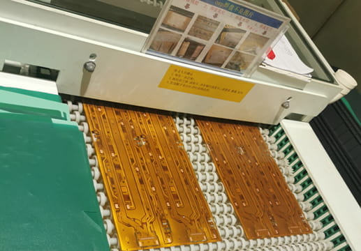
Circuit generation is in the toll-to-toll way, which means we etch circuits while rolling up the copper foil toll.
The long circuit generation line includes procedures of exposing > developing > checking > etching > checking > film stripping > checking. The maximum width of the copper foil we can etch is 250mm.
Step 3. Surface finish
OSP is the most affordable and common surface finish for flexible PCBs. Besides OSP, we can also apply the other surface finish immersion gold on flex PCBs.
Step 4. Automatic optical inspection (AOI)
After circuit generation, we have to make sure the circuits give no surface mistakes, such as short or open circuits.
Step 5. Cutting coverlay
Coverlay is the solder mask of flexible PCBs to protect the circuits and materials.
We need to cut the coverlay films to match the size of the flex PCB production panel. It is done in an automatic machine without human touching.
Step 6. Attaching coverlay
This is also done automatically without human touching. The coverlay films are attached to the copper foil while soldering the mask opening.
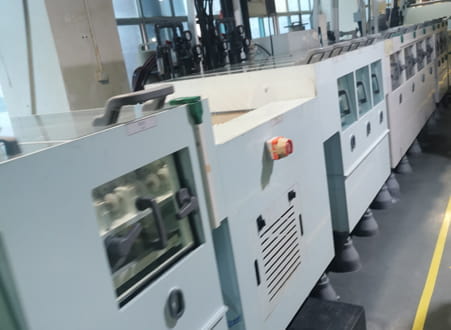
Step 7. Lamination
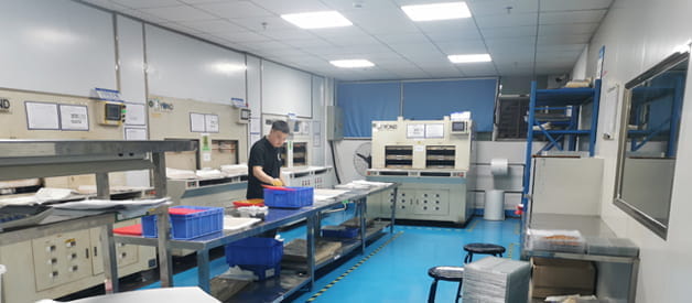
At this step, we put the flex PCBs in an oven to laminate the flex boards at high temperatures and pressure so that the copper layers and coverlay films form a whole.
Step 8. Silkscreen printing
At this step, we silkscreen print the characters, component codes, company names, and quality icons on the flex PCBs as you want.
Step 9. Electrical testing
Before electrical testing, we have already fabricated the custom jigs for testing the flex PCBs. At this step, we put the flex PCBs on the jigs for electrical testing to ensure the circuits work properly.
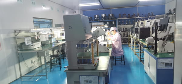
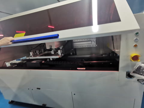
Step 10. Surface-mount (SMT) assembly
Before SMT assembly, we had already made custom jigs for fixing the flexible PCBs during the assembly process.
We place the flex PCB panel in a jig and then place it in an SMT assembly machine. The machine picks and places components on the flex PCB to become a flex PCBA.
For cell contact system uses, the components of a flex PCBA include small nickel sheets, NTC (negative temperature coefficient) thermistors, and connectors. We assemble components on the flex PCB while glue dispensing it.
Step 11. Cell contact system assembly
Before the cell contact system assembly, we completed the nickel sheets mold opening and prepared black films. At this step, we can thermally laminate the black films and nickel sheets on the top and bottom of the flex PCBA to make it a CCS module.
The other way is to laminate the nickel sheets and black films and then fix the flex PCBA at the bottom with screws and the blister trays process to make them a CCS module.
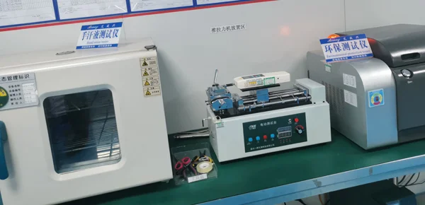
Step 12. Testing
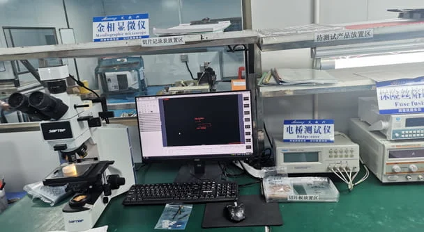
PCBONLINE has comprehensive tests to make sure the flexible PCBA or CCS modules we manufactured for you have the best quality.
The tests include electric tension testing, bending testing, hand sweat testing, environmental protection testing, metallographic microscope inspection, bridge testing, fuse fusing testing, DC resistance inspection, withstand voltage testing, impedance testing, and salt spray testing.
During the flex PCB fabrication, we can add flex PCB stiffeners to the boards. The stiffener materials include polyimide, FR4, and stainless steel.
Flex PCBs used in the cell contact system module for lithium-ion batteries for EVs have only one circuit layer and no plating through holes, so the above manufacturing process is simpler.
PCBONLINE also fabricates multilayer flex PCBs and transparent flex PCBs, and you can read our previous article to learn the fabrication process of flex PCBs that are more complex.
Conclusion
Cell contact system assembly is a process of manufacturing the flexible PCBA and laminating it with black films and nickel sheets to make it a CCS module. Automotive electronics are not complex to fabricate, but the quality standard is high because it involves human safety. If you are an automotive original equipment manufacturer and need flex PCBA and cell contact system assembly, don't miss the source factory manufacturer PCBONLNE.
©This article is an original work of the PCBONLINE team. Please indicate the author PCBONLINE if you reprint. If the article is reproduced without permission or indicating the author's source, PCBONLINE reserves the right to investigate the infringement.
Battery Management System Manufacturing at PCBONLINE.pdf
CCS Product Introduction - PCBONLINE.pdf


