
Since the 1990s, people have been crying out about the energy crisis of oil depletion and calling for using renewable energy such as solar and wind power. However, renewable energy generation is intermittent, and the power is high and low, unpredictable. Only until the 2010s has renewable energy been truly utilized until lithium-ion battery technology is developed and mature.
Battery cells, battery management systems (BMS), and cell contact systems (CCS) are important parts of a lithium-ion battery pack. This article gives a comprehensive introduction to the cell contact system, including its definition, applications, and how the CCS manufacturer PCBONLINE fabricates and tests it until delivery.
In this article:
Part 1: What is a Cell Contact System Part 2: Applications of Cell Contact System Part 3: CCS Manufacturing Processes and Specs Part 4: CTesting to CCS to Ensure Best Security Part 5: One-Stop CCS Manufacturer PCBONLINEWhat is a Cell Contact System
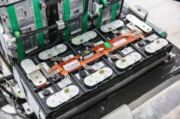
A cell contact system is a module connecting the battery cells and the BMS. Depending on your battery pack's demands, it may be above, between, or below the battery cells. In many cases, it is designed as the cover for the battery cells.
The CCS electrically and electronically connects the battery cells and the BMS, allowing for fast and slow charging. It also collects signals of temperature changes in the cells and reflects them to the BMS.
How can a CCS enable fast and slow charging and monitor cell temperature changes? First, you need to know the structures of a cell contact system.
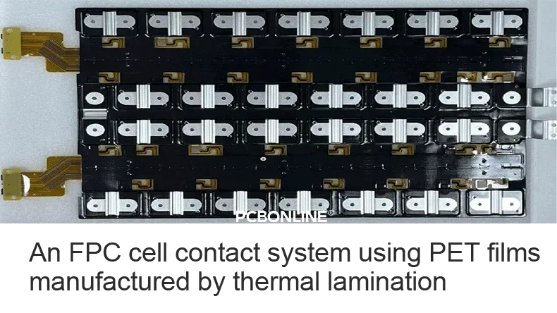
Currently, FPC (flexible printed circuit board) CCS is the most widely used cell contact system solution with mature technology. Its price is becoming increasingly affordable as flexible PCB costs fall. So, let's explore the structure of an FPC CCS.
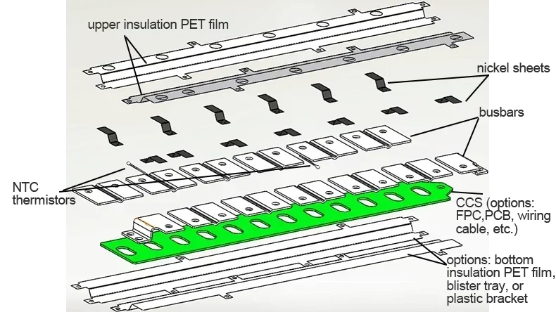
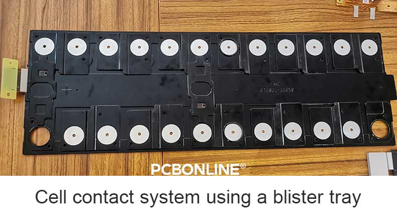
An FPC CCS consists of busbars, insulation PET films, and a flexible PCBA, which is a flex PCB surface mounted with negative temperature coefficient (NTC) thermistors, nickel sheets, and connectors. The cell contact system can also have a plastic bracket or blister tray at its bottom side.
In a cell contact system, the FPC and the busbar are connected through the nickel sheet; the nickel sheet and the FPC are soldered by SMT assembly, and the nickel sheet and the busbar are laser welded. Their connection strength requirements are below.
|
|
Shearing force
|
Peeling force |
|
Connection strength between nickel sheet and FPC
|
>100N
|
>25N
|
|
Connection strength between nickel sheet and copper bar
|
>300N
|
>60N
|
The connectors of the CCS connect to the BMS. The CCS monitors cell temperature changes through NTC thermistors.
An NTC thermistor's resistance changes non-linearly with temperature changes. It is placed near the nickel sheet, and the BMS sends a circuit current flowing through it. When the cells' temperature changes, the current that returns to the BMS changes, and the BMS can determine whether the battery temperature is within the normal range, too high, or too low. (In manufacturing, we require the cells to stay at a constant temperature of about 20 degrees as much as possible.)
Regarding charging, when the power is below about 90%, a large high-power current flows through the CCS' copper busbars to the battery cells. When the battery power reaches 90%, the battery pack turns to the slow charging mode. A small current (0.1A-0.5A) flows through the FPC PCBA.
Besides, the CCS can reflect the cell power to the BMS. During the battery pack testing, the BMS can determine which cell is not fully charged to ensure battery consistency.
An FPC CCS is highly integrated and comes with over-current insurance. It replaces the wiring harness module for the balanced management of a single battery. It is light in weight, strong in consistency, stable in performance, and easy to use in automated assembly.
Nowadays, you have a newer CCS solution option - integrated busbar CCS. It integrates the FR4 PCB or flex PCB with the busbars.
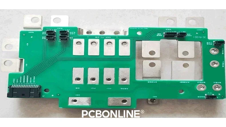
- Pros of integrated busbar CCS: Integrated design, high consistency, very high successful rate
- Cons of integrated busbar CCS: Its high price determines that this solution is only suitable for bulky production.
Applications of Cell Contact System
A cell contact system can be used in a power battery pack and an energy storage battery pack.
The power battery pack using a CCS is used in many kinds of vehicles, including:
Electric cars and hybrid electric cars,
Electric motorcycles,
Electric trucks,
Electric ships,
Special vehicles,
Electric logistics vehicles.
The energy storage battery pack using a CCS is used in all kinds of energy storage solutions, including:
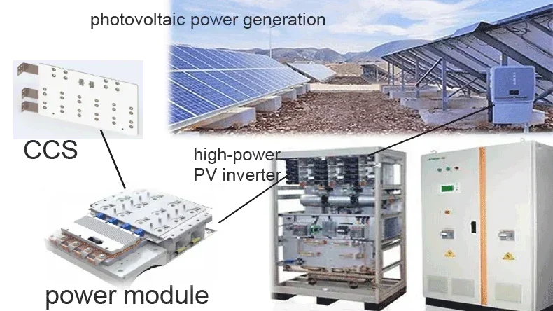
Household energy storage battery cabinets,
Solar photovoltaic (PV) power generation systems,
Wind power generation,
Grid-connected PV power generation for mains, etc.
CCS Manufacturing Processes and Specs
Let's still use the FPC cell contact system to show you the CCS manufacturing process.
Step 1. FPC fabrication
First, we manufacture the FPC. The FPC used in a CCS is usually single-layer or double-layer double-sided. The copper thickness of the FPC is 35μm. The normal thickness of a single-layer FPC is 0.2mm, and that of a double-layer double-sided FPC is 0.32mm.
Here is the specification table of the flexible PCB for the CCS.
|
Specs
|
FPC capabilities
|
|
FPC layer
|
Single-layer/single-layer double contacts/double-layer
|
|
Copper thickness
|
1oz/2oz (minimum 7µm)
|
|
Maximum size
|
Single-layer FPC: 1200mm*230mm
Double-layer FPC: 500mm*230mm |
|
Flex PCB thickness tolerance
|
10%
|
|
Trace width/space
|
Determined by the current to flow through, the maximum width/space 0.3mm
|
|
Dimensional tolerance
|
<1.5mm
|
|
Auxiliary material fitting tolerance
|
+/-0.2mm
|
|
Surface finish
|
OSP 0.2-0.5um
|
|
Bonding strength between nickel sheet and copper busbar
|
Shearing force>100N, peeling force>25N
|
|
Connector push and pull force
|
≥100N
|
|
FPC upper and lower insulation film withstand voltage
|
a3550VDC, 60s, leakage current ≤1mA
2000VAC, 60s, leakage current ≤2mA |
|
FPC upper and lower insulation film insulation
|
>500MΩ (1000VDC, 60s)
|
|
Loop resistance
|
Single loop internal resistance ≤1Ω
|
|
Working temperature
|
-40℃ to 125℃
|
|
FPC circuit withstand voltage
|
1600VDC, 60S, leakage ≤1mA; 1000VAC, 60S, leakage ≤1mA
|
|
The insulation between FPC circuits
|
>500MΩ (500VDC, 60s)
|
|
Salt spray resistance
|
5% NaCl solution for 96 hours, no effect on appearance and performance
|
|
Flame retardant
|
Complies with UL 94v-0
|
Step 2. FPC assembly
Then, we prepare all the materials for flexible PCB assembly, including FPCs, NTC thermistors, nickel sheets, connectors, and SMT assembly jigs and molds.
On the SMT assembly line specialized for CCS' FPC, the FPC is placed in a jig so that it won't move or lift during assembly. The FPC is silkscreen printed with solder paste and goes through the 3D solder paste inspection. Next, the NTC thermistors, nickel sheets, and connectors are picked and placed on the FPC. Then, the flex PCBA goes through the reflow soldering process, 3D automatic optical inspection (AOI), and 3D X-ray inspection. Later, we use Plasma to clean the FPC PCBA and dose glue to further fix the nickel sheet and NTC thermistor on the FPC. At the end of the FPC assembly, we have an in-circuit test of the PCBA and print a QR code on it, which contains all the manufacturing information for traceability.
All FPC assembly process above is automated.
Here is the specification table of the PCBA for the CCS.
|
|
FPC PCBA
|
PCBA
|
Cable wiring connection
|
|
|
Nickel sheet
|
Material
|
Pure nickel
|
Pure nickel
|
Pure nickel
|
|
Thickness
|
0.15mm-0.5mm
|
0.15mm-0.5mm
|
0.15mm-0.5mm
|
|
|
Performance
|
Good conductivity and low contact resistance
|
Good conductivity and low contact resistance
|
Good conductivity and low contact resistance
|
|
|
Size instructions
|
Length (10mm-200mm)*width (5mm-50mm)
|
Length (10mm-200mm)*width (5mm-50mm)
|
Length (10mm-200mm)*width (5mm-50mm)
|
|
|
Other description
|
Costly but its surface anti-oxidation
|
Costly but its surface anti-oxidation
|
Costly but its surface anti-oxidation
|
|
|
Note
|
Custom made
|
Custom made
|
Custom made
|
|
|
NTC thermistor
|
Type
|
Normal NTC
|
Normal NTC
|
drop-shaped NTC
|
|
Footprint
|
0603, 0402, or drop-shaped
|
0603, 0402, or drop-shaped
|
drop-shaping packaging
|
|
|
Specs
|
Choose different specs according to the usage
|
Choose different specs according to the usage
|
Choose different specs according to the usage
|
|
|
Size
|
Unified specification packaging
|
Unified specification packaging
|
/
|
|
|
Other description
|
It is a sensitive part and needs waterproof glue dosing
|
It is a sensitive part and needs waterproof glue dosing
|
Is a sensitive part with mature technology
|
|
|
Note
|
Standard part
|
Standard part
|
/
|
|
|
Connector
|
Type
|
SMD
|
SMD
|
SMD
|
|
Pin quantity
|
12-60
|
12-60
|
12-60
|
|
|
Current/voltage
|
Current 3A-5A, voltage 1500V-3500V
|
Current 3A-5A, voltage 1500V-3500V
|
Current 3A-5A, voltage 1500V-3500V
|
|
|
Size
|
Unified specification packaging
|
Unified specification packaging
|
Unified specification packaging
|
|
|
Other description
|
Device with mature technology
|
Device with mature technology
|
Device with mature technology
|
|
|
Note
|
Standard part
|
Standard part
|
Standard part
|
|
|
FPC/PCB/wiring cable
|
Material
|
RA Cu + PI base and coverlay
|
FR4 PCB
|
Copper wire, aluminum wire, or silver clad copper
|
|
Thickness
|
0.13mm-0.3mm
|
1.0mm-5.0mm
|
Line 15-35
|
|
|
Line width/space
|
Depending on the usage environment
|
Depending on the usage environment
|
different wire sizes according to design requirements
|
|
|
Size
|
Length (10mm-1500mm)*width (5mm-200mm)
|
Length (10mm-1500mm)*width (5mm-200mm)
|
/
|
|
|
Other description
|
Reliable and adaptable
|
Reliable but the solder mask may leak electricity
|
Reliable and adaptable
|
|
|
Note
|
Custom made
|
Custom made
|
/
|
|
Step 3. CCS assembly
There are two technologies for CCS assembly: thermal lamination and thermal riveting.
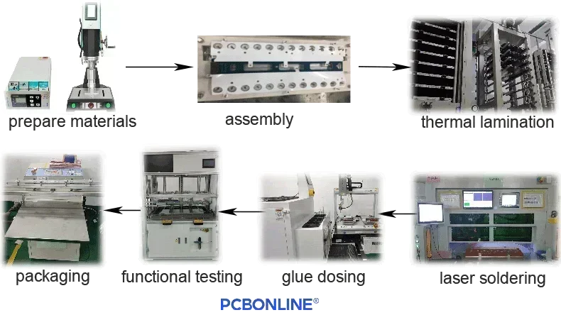
Thermal lamination is for cell contact systems using insulation films. The CCS assembly process includes: preparing all materials and molds > assembly > thermal lamination > laser soldering the nickel sheets and copper busbars > functional testing > packaging.
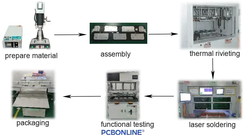
Thermal riveting is for cell contact system assembly using a blister tray or plastic bracket. The CCS assembly process includes: preparing all materials and molds > assembly > thermal riveting > laser soldering the nickel sheets and copper busbars > dosing glue > functional testing > packaging.
Here are the CCS manufacturing specifications at PCBONLINE.
|
|
Thermal lamination technology CCS
|
Thermal riveting technology CCS
|
| Busbar material | Copper busbar or aluminum busbar. If it is an aluminum busbar, the material is pure aluminum, thickness 0.1mm-5.0mm, easy to process and solder, good conductivity, low cost, and lightweight; the size and thickness depend on current requirements | |
|
Insulation solution
|
PET films: 0.13mm-0.3mm thick; color can be black, color, or blue; low cost; light weight | Blister tray: PC+ABS/PC/PP material; thickness 0.5mm-1.0mm; reliable performance; the mold opening cost is low and the cycle is short. |
| Plastic bracket: PC+ABS material; thickness 1.2mm+; stable performance; the mold opening cost is high and the cycle is long. | ||
|
CCS structure
|
||
| FPC PCBA + busbar + PET films | FPC PCBA + busbar + blister tray | |
| PCBA + busbar + blister tray | ||
| PCBA + busbar + PET films | Wiring cables + busbar + blister tray | |
| FPC PCBA + busbar + plastic bracket | ||
| Wiring cables + busbar + PET films | PCBA + busbar + plastic bracket | |
| Wiring cable + busbar + plastic bracket | ||
Note: We recommend cell contact system design using the PET films or blister try as its molding cost is low.
Testing to CCS to Ensure Best Security
After the cell contact system fabrication, we have comprehensive and rigorous tests to ensure the best quality of the CCS module. We have to make all efforts to strive for zero issues in the CCS and the battery pack, as it matters not only to our reputation but, most importantly, to people's lives and property safety.
You can see a series of our testing and the requirements to the CCS.
|
Testing items
|
Testing standard
|
Testing requirement
|
|
Appearance quality
|
GB/T5095.2-1997
|
There are no cracks, pieces, swelling, burrs, or other mechanical damage in appearance; the markings are complete, correct, and clear; the welding position is free of defects such as empty welding, missing welding, and welding slag.
|
|
Weight control
|
>300N
|
The weight meets the drawing requirements.
|
|
Structure size
|
>300N
|
The structure, appearance, and installation dimensions should comply with the requirements of the technical drawings.
|
|
Forbidden or restricted substances
|
>300N
|
Meet the requirements for forbidden and restricted substances in automotive products.
|
|
Flame retardant
|
>300N
|
Meet fire test or UL94-V0.
|
|
Shear force of busbar soldering
|
>300N
|
The weld will not fall off when the shearing force ≥1000N
|
|
Nickel sheets
|
>300N
|
Provide nickel sheet material certificate
|
|
Busbar
|
>300N
|
Provide aluminum bar material certificate
|
|
Pull-off force of nickel sheet and busbar
|
>300N
|
Shearing force ≥300N, peeling force ≥50N
|
|
Pull-off force of nickel sheet and FPC/PCB
|
>300N
|
90° peel test method, not less than 1.5N/mm (the peeling force of this sample is not less than 10.5N)
|
|
Insulating film peeling force
|
>300N
|
90° peeling force of PET insulation film from FPC and palladium sheet, respectively, not less than 0.7N/mm
|
|
Salt spray resistance
|
>300N
|
>60N
|
| Waterproof testing, short-time high temperature, cold/hot shocks, Constant heat and humidity test (±85℃), thermal aging, and 7 electrical performance tests to long-time working, fuse, NTC resistance, short/open circuits, insulation voltage withstand, voltage withstand between circuits, and insulation resistance | ||
One-Stop CCS Manufacturer PCBONLINE
PCBONLINE provides one-stop cell contact system manufacturing, including research and development. We have complete equipment specialized for CCS manufacturing and testing. Our experienced engineers can also design the CCS and solve technical issues.
If you haven't completed your battery pack design, including the BMS and the CCS, you can let us design for you. You can draw the outline of the battery pack and tell us the line connection sequence of the cells and CCS; if possible, send the 3D drawing of the entire pack so that we can understand your CCS and BMS demands.
We take care of CCS manufacturing traceability and print a QR code on the FPC/PCB/integrated busbar PCBA that contains all the information on the manufacturing operations, time, and specs.
Quality is paramount. We focus on weight control to ensure the consistency of all the FPC/PCB/integrated busbars, nickel sheets, NTCs, connectors, insulation films, copper busbars, and a blister tray/plastic bracket.
All the inspections during the FPC/PCB/integrated busbar assembly for the CCS are 3D, including SPI, AOI, and X-ray. The high-accuracy images and dimensions are retained for 15 years for traceability.
We not only provide one-stop manufacturing for the CCS but also can design the CCS and BMS according to your battery pack demands.
We have strong manufacturing capabilities and technical experience in new energy automotive and energy storage electronics, especially thermal and electric management.
We provide one-on-one engineering support and can send a CCS sample to you for free if you plan for bulky production. Please get in touch with us by email at info@pcbonline.com if you have any CCS demands.
Conclusion
A CCS module not only connects the battery cells and the BMS but also collects signals of cell temperature change and power. It is also the pathway for fast and slow charging. With the advancement of CCS, BMS, and battery technology, power batteries and energy storage batteries have found many applications, such as EVs, household energy storage, PV power generation, etc. It not only allows humans to obtain sustainable energy but also protects the environment and reduces carbon emissions. If you want to develop your products using a cell contact system, please get in touch with PCBONLINE.
Battery Management System Manufacturing at PCBONLINE.pdf
CCS Product Introduction - PCBONLINE.pdf


