
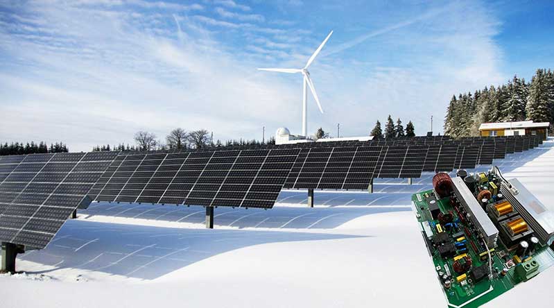
In remote areas, off-grid, and energy-optimization-required scenarios, solar energy can be applied for powering. A smart solar microgrid management system using Arduino Uno to collect, manage, and distribute energy can pave the way for home and commercial-use solar energy systems. When you finish the design, you can have the solar energy system manufactured into real products through PCB assembly services.
This project presents a compact, cost-effective microgrid controller built around an Arduino Uno. It automatically manages three power sources: solar panels, a battery bank, and grid backup, and two types of loads (DC and AC).
By measuring voltage and current at key points, the system continuously computes power flows, prioritizes solar energy, charges the battery with surplus photovoltaics, and protects against over‑discharge. An optional Wi‑Fi module enables remote monitoring, while an LCD offers on-site feedback.
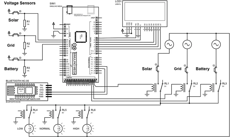
System Block Diagram
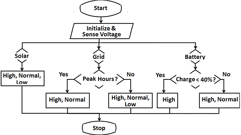
Flow Chart
Hardware Components
|
Item
|
Role
|
|
Arduino Uno
|
Central controller
|
|
ACS712 current sensors
|
Measure current on PV, battery, grid, DC & AC loads
|
|
Voltage divider sensor
|
Scale and read voltages (0–25 V range)
|
|
5V relay modules
|
Route power from sources to loads and battery charging
|
|
12 V battery (30 Ah)
|
Energy storage
|
|
Solar panel (100 W, 12 V)
|
Renewable energy input
|
|
Grid input (200 W max)
|
Backup power source
|
|
16×2 I²C LCD
|
On-board status display
|
|
ESP8266 Wi-Fi module
|
HTTP telemetry (optional)
|
Sensor & Relay Interfacing
1. Voltage sensing
Each analog input (A0–A2) reads a scaled voltage via a resistor divider.
2. Current sensing
ACS712 outputs 2.5 V at zero current; scale per sensor specs
3. Relays
Source relays (pins 22, 23, 24): select PV, grid, or battery.
Load relays (pins 25, 26): switch DC or AC load on/off.
Charge relay (pin 27): routes surplus PV to the battery.
All relays use active-low logic.
Source Code
//-------------------------------------- LCD
#include <LiquidCrystal.h>
// initialize the LCD library with the numbers of the interface pins
LiquidCrystal lcd(12, 11, 10, 9, 8, 7);
//-------------------------------------- VOLTAGE SENSORS
const int Solar_Sen_Pin = A0;
const int Grid_Sen_Pin = A1;
const int Battery_Sen_Pin = A2;
int Solar_Val;
int Grid_Val;
int Battery_Val;
float Solar_Volts;
float Grid_Volts;
float Battery_Volts;
//-------------------------------------- RELAYS
const int Relay_Solar = A8;
const int Relay_Grid = A9;
const int Relay_Gnd = A10;
const int Relay_Battery = A11;
const int Relay_BatteryN = A12;
const int Relay_High = A13;
const int Relay_Normal = A14;
const int Relay_Low = A15;
//-------------------------------------- BUTTONS
const int Button_PH = 2;
const int Button_B40 = 3;
const int Button_High = 4;
const int Button_Normal = 5;
const int Button_Low = 6;
int ButtonState_PH;
int ButtonState_B40;
int ButtonState_High;
int ButtonState_Normal;
int ButtonState_Low;
//-------------------------------------- BLUETOOTH
char Blue_Val = 0;
void setup() {
Serial.begin(9600);
// LCD init
lcd.begin(20, 4);
lcd.clear();
lcd.setCursor(0, 0); lcd.print("SMART HYBRID");
lcd.setCursor(0, 1); lcd.print("ENERGY MANAGEMENT");
lcd.setCursor(0, 2); lcd.print("SYSTEM USING");
lcd.setCursor(0, 3); lcd.print("ARDUINO");
delay(5000);
lcd.clear();
lcd.setCursor(0, 0); lcd.print("DESIGNED BY:");
lcd.setCursor(0, 1); lcd.print("ASFANDIYAR TARIQ");
lcd.setCursor(0, 2); lcd.print("AND");
lcd.setCursor(0, 3); lcd.print("SAAD KHAN");
delay(5000);
lcd.clear();
// Sensor pins
pinMode(Solar_Sen_Pin, INPUT);
pinMode(Grid_Sen_Pin, INPUT);
pinMode(Battery_Sen_Pin, INPUT);
// Relay pins
pinMode(Relay_Solar, OUTPUT);
pinMode(Relay_Grid, OUTPUT);
pinMode(Relay_Gnd, OUTPUT);
pinMode(Relay_Battery, OUTPUT);
pinMode(Relay_BatteryN, OUTPUT);
pinMode(Relay_High, OUTPUT);
pinMode(Relay_Normal, OUTPUT);
pinMode(Relay_Low, OUTPUT);
digitalWrite(Relay_Solar, HIGH);
digitalWrite(Relay_Grid, HIGH);
digitalWrite(Relay_Gnd, HIGH);
digitalWrite(Relay_Battery, HIGH);
digitalWrite(Relay_BatteryN, HIGH);
digitalWrite(Relay_High, HIGH);
digitalWrite(Relay_Normal, HIGH);
digitalWrite(Relay_Low, HIGH);
// Button pins
pinMode(Button_PH, INPUT_PULLUP);
pinMode(Button_B40, INPUT_PULLUP);
pinMode(Button_High, INPUT_PULLUP);
pinMode(Button_Normal, INPUT_PULLUP);
pinMode(Button_Low, INPUT_PULLUP);
// Bluetooth init (only warning for Uno)
#if defined(USART1_RX_vect) || defined(UBRR1H)
Serial1.begin(9600);
#else
Serial.println("Warning: Serial1 not supported on this board.");
#endif
}
void loop() {
#if defined(USART1_RX_vect) || defined(UBRR1H)
if (Serial1.available() > 0) {
Blue_Val = Serial1.read();
Serial.println(Blue_Val);
}
#endif
//-------------------------------------- Read voltage sensor values
Solar_Val = analogRead(Solar_Sen_Pin);
Grid_Val = analogRead(Grid_Sen_Pin);
Battery_Val = analogRead(Battery_Sen_Pin);
// Assuming 11:1 voltage divider
Solar_Volts = (Solar_Val * 5.0 / 1023.0) * 11.0;
Grid_Volts = (Grid_Val * 5.0 / 1023.0) * 11.0;
Battery_Volts = (Battery_Val * 5.0 / 1023.0) * 11.0;
//-------------------------------------- Read button states
ButtonState_PH = digitalRead(Button_PH);
ButtonState_B40 = digitalRead(Button_B40);
ButtonState_High = digitalRead(Button_High);
ButtonState_Normal = digitalRead(Button_Normal);
ButtonState_Low = digitalRead(Button_Low);
//-------------------------------------- Debug prints
Serial.print("Solar Volts: "); Serial.println(Solar_Volts);
Serial.print("Grid Volts: "); Serial.println(Grid_Volts);
Serial.print("Battery Volts: "); Serial.println(Battery_Volts);
//-------------------------------------- Display source availability
lcd.setCursor(0, 0);
if (Solar_Volts >= 2) lcd.print("S: ON "); else lcd.print("S:OFF ");
lcd.setCursor(7, 0);
if (Grid_Volts >= 2) lcd.print("G: ON "); else lcd.print("G:OFF ");
lcd.setCursor(14, 0);
if (Battery_Volts >= 2) lcd.print("B: ON "); else lcd.print("B:OFF ");
//-------------------------------------- Handle different conditions
if (Solar_Volts >= 2 && Grid_Volts >= 2 && Battery_Volts >= 2) {
lcd.setCursor(0, 1); lcd.print("SYSTEM: SOLAR ");
digitalWrite(Relay_Solar, LOW);
digitalWrite(Relay_Gnd, LOW);
digitalWrite(Relay_Grid, HIGH);
digitalWrite(Relay_Battery, HIGH);
digitalWrite(Relay_BatteryN, HIGH);
} else if (Solar_Volts < 2 && Grid_Volts >= 2 && Battery_Volts >= 2) {
lcd.setCursor(0, 1); lcd.print("SYSTEM: GRID ");
digitalWrite(Relay_Grid, LOW);
digitalWrite(Relay_Gnd, LOW);
digitalWrite(Relay_Solar, HIGH);
digitalWrite(Relay_Battery, HIGH);
digitalWrite(Relay_BatteryN, HIGH);
} else if (Solar_Volts < 2 && Grid_Volts < 2 && Battery_Volts >= 2) {
lcd.setCursor(0, 1); lcd.print("SYSTEM: BATTERY ");
digitalWrite(Relay_Battery, LOW);
digitalWrite(Relay_BatteryN, LOW);
digitalWrite(Relay_Grid, HIGH);
digitalWrite(Relay_Solar, HIGH);
digitalWrite(Relay_Gnd, HIGH);
} else if (Solar_Volts >= 2 && Grid_Volts < 2 && Battery_Volts >= 2) {
lcd.setCursor(0, 1); lcd.print("SYSTEM: SOLAR ");
digitalWrite(Relay_Solar, LOW);
digitalWrite(Relay_Gnd, LOW);
digitalWrite(Relay_Grid, HIGH);
digitalWrite(Relay_Battery, HIGH);
digitalWrite(Relay_BatteryN, HIGH);
} else if (Solar_Volts < 2 && Grid_Volts < 2 && Battery_Volts < 2) {
lcd.clear();
lcd.setCursor(0, 0); lcd.print("NO SOURCE AVAILABLE");
digitalWrite(Relay_Solar, HIGH);
digitalWrite(Relay_Grid, HIGH);
digitalWrite(Relay_Battery, HIGH);
digitalWrite(Relay_BatteryN, HIGH);
digitalWrite(Relay_Gnd, HIGH);
return;
}
//-------------------------------------- Output Mode Control
if (Blue_Val == '9') {
digitalWrite(Relay_High, LOW);
digitalWrite(Relay_Normal, LOW);
digitalWrite(Relay_Low, LOW);
} else if (Blue_Val == 'I') {
digitalWrite(Relay_High, HIGH);
digitalWrite(Relay_Normal, HIGH);
digitalWrite(Relay_Low, HIGH);
} else {
if (ButtonState_High == 0 || Blue_Val == '1') {
digitalWrite(Relay_High, LOW);
digitalWrite(Relay_Normal, HIGH);
digitalWrite(Relay_Low, HIGH);
} else if (ButtonState_Normal == 0 || Blue_Val == '2') {
digitalWrite(Relay_High, HIGH);
digitalWrite(Relay_Normal, LOW);
digitalWrite(Relay_Low, HIGH);
} else if (ButtonState_Low == 0 || Blue_Val == '3') {
digitalWrite(Relay_High, HIGH);
digitalWrite(Relay_Normal, HIGH);
digitalWrite(Relay_Low, LOW);
} else {
digitalWrite(Relay_High, HIGH);
digitalWrite(Relay_Normal, HIGH);
digitalWrite(Relay_Low, HIGH);
}
}
//-------------------------------------- Additional display info
lcd.setCursor(0, 2);
if (ButtonState_PH == 0)
lcd.print("Peak Hours: YES ");
else
lcd.print("Peak Hours: NO ");
lcd.setCursor(0, 3);
if (ButtonState_B40 == 0)
lcd.print("Battery < 40% ");
else
lcd.print("Battery > 40% ");
delay(1000);
}
Mobile Monitoring App
Configure the App
- Install the APK on your Android device.
- Open it and look for a "Settings," "Server," or "Preferences" menu.
- Enter the Base URL as http://
(e.g. http://192.168.4.1). - Enter the Endpoint Path as /update.
- Choose POST to match your code.
- Select JSON if you're returning application/json.
Test the connection
- Make sure your phone is on the same Wi‑Fi network (or connected to the ESP's AP).
- In the app, hit Connect or Refresh.
- You should see live numbers for total power, PV, and battery.
Troubleshoot common issues
- No response/timeout: Verify the ESP's IP (print it over Serial on boot).
- Malformed data: Open http://
/update in a browser or Postman to confirm the exact response.
Once your ESP and APK speak the same language, the app will display real-time microgrid telemetry with no extra coding on your part.
Partner with PCBONLINE for Solar Energy System OEM Manufacturing
OEM original equipment manufacturing services include prototypes, PCB printed circuit board fabrication, component sourcing, PCB assembly, enclosures, box-build assembly, burn-in, IC programming, functional testing, and other value-added services. To have your solar energy systems or equipment manufactured from scratch to finished products under one roof, partner with the OEM PCBA manufacturer PCBONLINE.

Founded in 1999, the OEM PCB manufacturer, PCBONLINE, has two large advanced PCB manufacturing bases independently fabricating all types of PCBs, one EMS (electronic manufacturing service) PCB assembly factory with two component warehouses, stable supply chains, and an R&D team. Besides, it keeps long-term cooperation with the top 3 mold/enclosure manufacturers in China to provide the molds, jigs, and enclosures for full box-build solutions.
PCBONLINE has rich R&D experience for solar energy systems, such as battery management systems, cell contact systems, enclosure designs, etc.
Turnkey PCB manufacturing and assembly for solar energy systems from prototypes to bulk production.
Our experienced R&D and engineering teams provide one-on-one support, solving technical and non-technical challenges while offering optimization suggestions to ensure your project runs smoothly from start to finish.
High-quality PCBA manufacturing certified with ISO 9001:2015, ISO 14001:2015, IATF 16949:2016, RoHS, REACH, UL, and IPC-A-610 Class 2/3.
When your project enters the bulky production stage, PCBONLINE refunds the fees of prototyping, including its value-added services.
No matter what quantity of boards you order, PCBONLINE prioritizes quality. To get a quote from the OEM PCBA manufacturer PCBONLINE, contact info@pcbonline.com.
Conclusion
The smart solar microgrid management system project in this article uses an Arduino Uno and simple sensors. It only provides the example codes without the schematics, so if you need R&D and OEM manufacturing, partner with the OEM PCBA manufacturer, PCBONLINE. By partnering with PCBONLINE, you can safely and successfully turn standalone solar and battery hardware into a self‑regulating microgrid, maximizing solar usage, safeguarding your battery, and keeping your solar energy product running smoothly.
PCB assembly at PCBONLINE.pdf


