
In a battery pack, a CCS (cell contact system, also called cell connection system) connects the battery cells and the BMS (battery management system) and monitors the voltage and temperature changes of the cells to the BMS. It enables fast and slow charging of the battery cells and ensures the safety of the battery pack. How to manufacture the CCS? There are four solutions:
- Cable wiring
- PCB (printed circuit board) CCS
- FPC (flexible printed circuit) CCS
- FDC (flexible die-cutting circuit) CCS
This article focuses on the FDC CCS and provides a comprehensive guide to the flexible die-cutting FDC technology, including the FDC CCS manufacturing process, a comparison of the FDC CCS with the other CCS solutions, and CCS manufacturer PCBONLINE providing all the CCS solutions from R&D to CCS and BMS manufacturing.
In this article:
Part 1: What is an FDC CCS? Part 2: Comparison between FDC, FPC, PCB, and Wring Cable CCS Solutions One-stop CCS Manufacturer PCBONLINE with R&D Capabilities for 4 CCS Solutions Part 4: FDC Flexible Die-Cutting CCS Manufacturing ProcessWhat is an FDC CCS?
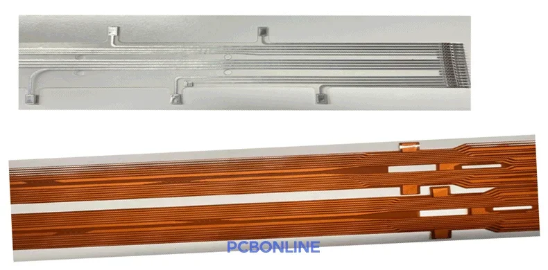
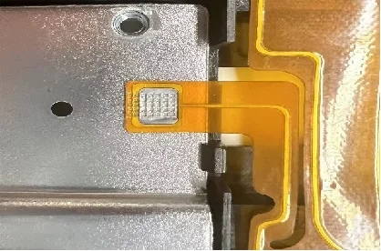
An FDC, or flexible die-cutting circuit, is a flexible circuit board made by cutting the PI (polyimide) film and aluminum foil laminated substrate material with rotary dies or flat dies. It can only be single-sided. Similar to an FPC, an FDC can bend, fold, twist, and stretch in a compact space. It requires less manufacturing complexity and can be an alternative to a single-sided FPC.
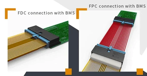
Currently, the mainstream solution for a CCS in the battery pack is an FPC CCS. Since a CCS doesn't have many components, why not use an FDC to replace a single-sided FPC for the CCS to reduce manufacturing complexity and save costs?
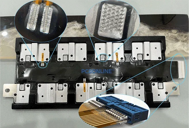
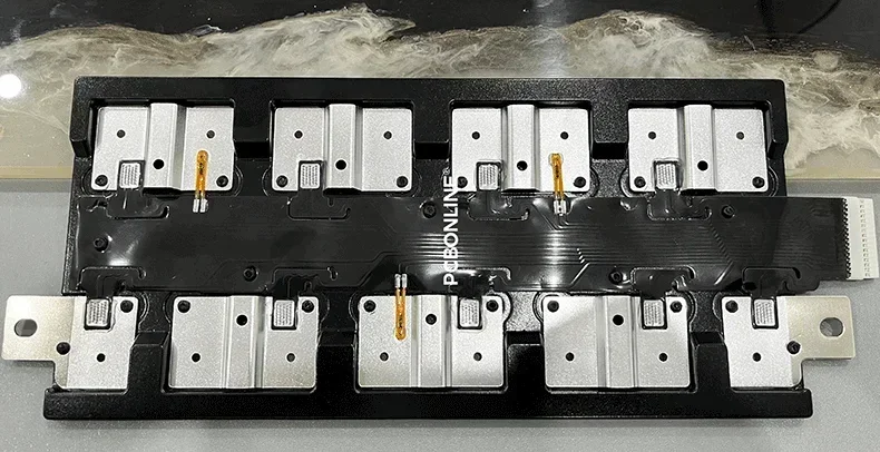
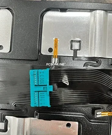
An FDC CCS is a flexible die-cutting circuit connected with IDC (insulation displacement) connectors and ultrasonically welded with negative temperature coefficient (NTC) thermistors. The NTCs are encapsulated for waterproofing. Then the FDC is ultrasonically welded with insulation films/blister brackets and aluminum/copper busbars to be the final FDC CCS.
Compared with FPC CCS manufacturing, an FDC CCS solution has many advantages, including:
Less manufacturing complexity: The FDC CCS solution doesn't require SMT soldering to connect the NTCs and connectors, thermal lamination to attach the insulation film/blister bracket, or laser welding to connect the busbars. Fitting IDC connectors and ultrasonic welding are much more straightforward and less complex.
Fewer manufacturing costs: FDC CCS manufacturing costs only about 1/3 of the FPC CCS solution. Besides less manufacturing complexity, the FDC CCS requires fewer connectors to connect with the BMS and no nickel sheets or FPC stiffeners. Most importantly, in the prototyping stage, the FDC CCS solution doesn't require custom jigs.
More quality reliability: IDC connection in the FDC CCS doesn't require soldering, so soldering issues that may happen in FPC, PCB, and wiring cable CCS solutions can't occur. Besides, bubbles may occur in all the other CCS solutions when applying solder paste to connect the NTCs, nickel sheets, and blister bracket. In contrast, ultrasonic welding in the FDC CCS solution integrates the molecular of the NTCs, blister bracket, and aluminum busbars with the FDC, preventing any bubbles, thus no potential risk.
Environmentally friendly: FDC manufacturing is mechanically die cutting, so there's no etching in the PCB and FPC manufacturing process. There are no corrosive chemicals used in the FDC CCS manufacturing process, so it is eco-friendly.
Now you understand what an FDC CCS is, let's see a brief comparison between the four CSS solutions, which all can achieve monitoring of the cells and connection between the BMS and cells of the battery pack.
Comparison between FDC, FPC, PCB, and Wring Cable CCS Solutions
When the battery pack was used for powering electric bikes and solar energy storage decades ago, wiring cables were used to connect the battery cells. As more vehicles like cars and boats started to be powered by electricity, and renewable energy storage systems started to require consistent and stable power, the BMS system emerged.
Back in the first, the wiring cable CCS was invented first, which used multiple wiring cables to connect the NTCs, battery cells, each other, and finally the BMS. It is heavy and takes up a lot of space.
Later, FR4 PCB came into play to replace the wiring cables. It takes less space and weight than wiring cables. However, it lacks flexibility and is still heavy.
Then the FPC CCS emerged, which is now the mainstream CCS solution and, over the past years, has proved its efficiency and success by many EV cars and solar/wind energy storage projects for bulk production. Thanks to the flexible PCB, the FPC CCS is lightweight and suitable for compact spaces. However, its manufacturing process includes 21 steps, which are complex and costly.
The FDC CCS is the newest CCS solution. It is as lightweight and flexible as the FPC CCS, and its manufacturing process is less complex, more environmentally friendly, and saves about 1/3 costs of the FPC solution. However, it is still being verified by the market.
Here is a comparison table of the four CCS solutions.
|
PCB copper thickness
|
Pros
|
Cons
|
Market application
|
Costs
|
|
Wiring cable CCS
|
Stable signal transmission, high reliability, low costs, mature technology
|
Low automation, low manufacturing efficiency, poor consistency of quality due to human factors
|
It is more commonly used in the field of energy storage.
|
Middle
|
|
PCB CCS
|
Stable signal transmission, high reliability, neat structure, high automation, suitable for bulky production
|
Rigid structure with poor ductility, structural space limit, needs strict testing due to potential soldering issues and bubbles, manufacturing is not environmentally friendly
|
It is more commonly used in the field of energy storage.
|
Middle
|
|
FPC CCS
|
Stable signal transmission, high reliability, lightweight and thin, neat structure, high automation, suitable for bulky production
|
Complex manufacturing process with 21 steps, long manufacturing cycle, needs strict testing due to potential soldering issues and bubbles, manufacturing is not environmentally friendly
|
Mainstream CCS solution for power battery packs for vehicles like cars and boats
|
High
|
|
FDC CCS
|
Fewer manufacturing steps of 10, no SMT and laser soldering, no nickel sheets, low costs, requires no jigs in prototyping, no pollution in manufacturing, suitable for bulky production
|
Still being verified
|
Still being verified
|
Low
|
One-stop CCS Manufacturer PCBONLINE with R&D Capabilities for 4 CCS Solutions
No matter what CCS solutions you are looking for, FDC, FPC, PCB, or wiring cables, you can work with the CCS and BMS Manufacturer PCBONLINE for R&D and one-stop manufacturing.
The R&D for the CCS is a systematic work. It involves the appearance and dimension design of the battery pack and layout of the cell groups, so the R&D team from PCBONLINE needs to work with your mechanical engineers for the CCS solution design. PCBONLINE only charges $1,000-$2,000 for the R&D of your CCS, BMS, or battery pack project.
If you want to buy the custom-made aluminum/copper busbars, nickel sheets, wiring cables, NTCs, and standard BMS for your CCS or battery pack project, PCBONLINE can also supply them to you.
Founded in 1999, PCBONLINE has two advanced PCB manufacturing bases, one turnkey PCB assembly factory, stable material and component supply chains, and long-term cooperation with the top 3 mold and enclosure manufacturers in China for jigs/fixtures, molds, and enclosures.
|
FDC capabilities
|
Processing parameters
|
|
Equipment widths
|
250mm
|
|
Processable aluminum thickness
|
0.018mm-0.1mm
|
|
Maximum rotary die diameter
|
400mm
|
|
Minimum line width/spacing
|
0.3mm
|
|
Fuse width
|
Die cutting 0.12mm, laser 0.1mm
|
|
Minimum solder mask opening of the coverlay
|
0.6mm (round hole, square hole)
|
|
Line width processing accuracy
|
±0.03mm
|
|
Cutting seam processing accuracy
|
±0.1mm
|
|
Fitting alignment accuracy
|
±0.2mm
|
|
Outline hole to line processing accuracy
|
±0.2mm
|
|
Minimum spacing from outline edge to board edge
|
2mm
|
|
Thermal lamination roller temperature control
|
Temperature uniformity ±5℃
|
|
FDC appearance
|
Lines are neat and smooth, no jumping edges, no gaps, no copper chips
|
|
Coverlay appearance
|
No bubbles or wrinkles
|
The applications PCBONLINE can provide CCS for include:
- Low-speed vehicles ( < 70km/h): golf carts, electric motorcycles (oil-to-electric), electric forklifts, electric wheelchairs, logistics robots, electric tricycles
- Boats (oil-to-electric): Yachts, small cruise ships, motorboats, scenic sightseeing boats, small and medium-sized cargo ships, electric law enforcement vessels for the Coast Guard
- Industrial energy storage (home & commercial storage): outdoor mobile power supply, household energy storage, commercial energy storage, container-type large energy storage, battery module for battery swap station, large energy storage power station
The CCS and custom BMS manufacturing from PCBONLINE are certified with ISO 9001:2015, ISO 14001:2015, ISO 16949:2016, RoHS, REACH, UL, and IPC-A-610 Class 3. However, PCBONLINE can't provide CCS manufacturing for electric cars, as the car-grade CCS standard is beyond IPC Class 3 and has a 15-year traceable record requirement. If you need busbars and wiring cables for your car-grade CCS, PCBONLINE can supply them to you.
Design: appearance and structural design for the battery pack, PCB/FPC layout of the CCS, BMS design, and verification.
Manufacturing: independent PCB/FPC manufacturing for the CCS, CCS assembly, including ultrasonic welding and laser welding
Components supply: copper busbars (including flexible copper busbars), aluminum busbars, blister and injection molding brackets, standard BMS, current-carrying SMT copper strips, wiring cables
Besides CCS and components, PCBONLINE also provides PCB and PCBA manufacturing for the custom BMS to manage the battery pack. We have successfully manufactured many CCS and BMS projects, and have rich R&D and manufacturing experience. To get a quote for CCS, BMS, or related components, please send your inquiry by email to info@pcbonline.com.
FDC Flexible Die-Cutting CCS Manufacturing Process
It takes only 10 steps to manufacture and assemble the FDC flexible die-cutting circuit for the cell connection system.
Among the 10 FDC manufacturing steps, the second step essentially includes 5procedures. Below are the steps.
Step 1. Sending materials on the line
The first step is preparing all the aluminum foils and PI films and sending them to the production line in rolls.
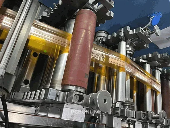
Step 2. die cutting
For small-batch FDC manufacturing, we use flat dies to cut the materials. For bulky production, we use rotary dies.
Die cutting the FDC includes 5 procedures here: die cutting the aluminum foil in the circuit graphic > attaching the PI film to the top of the aluminum foil > attaching the PI film to the bottom of the aluminum foil > thermal lamination to form the FDC > die cutting the FDC for the outline.
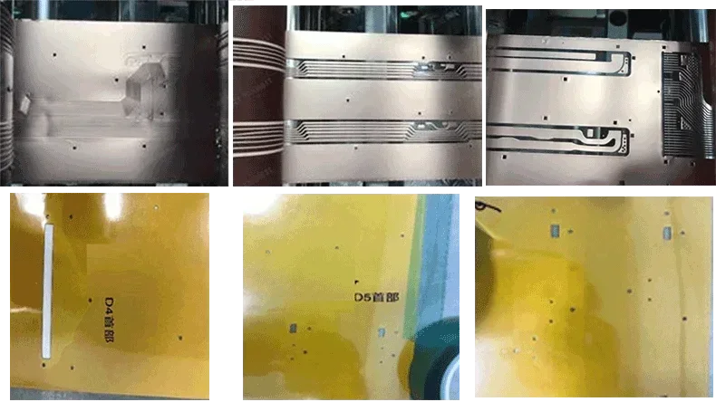
Step 3. AOI inspection
After the circuit is formed, the FDC goes to the AOI (automated optical inspection) machine, which scans the surface of the FDC and compares it with the reference appearance. A quality control worker will also visually check the FDC.
Step 4. Coverlay lamination
A coverlay is an insulation film consisting of a PI layer and a hot-melt adhesive. The FDC is laminated with the coverlay on the top side.
Step 5. Spray print legends
Legends, including words, symbols, component codes, and logos, are spray printed on the FDC for identification.
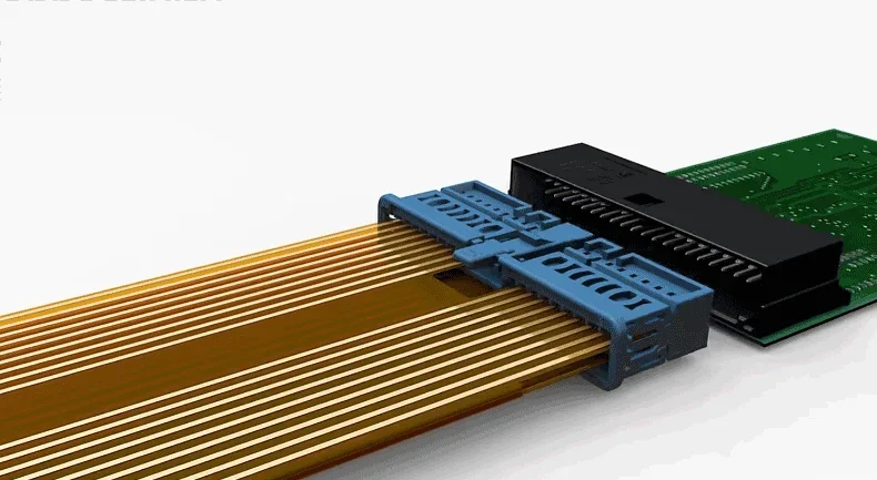
Step 6. Fitting IDC connectors
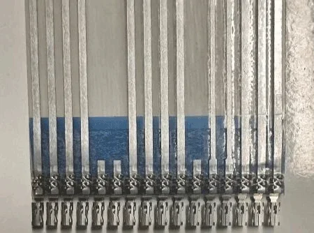
Insulation displacement IDC connectors belong to crimped connectors. They allow for electrical connection without stripping the wire insulation. An IDC terminal features a U-shaped metal slot or sharp blade structure that pierces the insulation layer and makes direct contact with the conductor inside.
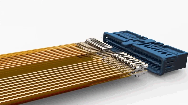
The IDC terminal pierces the coverlay and PI films to connect the FDC circuit, then is fitted with a plastic protection case to become the connector.
Step 7. Ultrasonic welding NTC
NTC thermistors are welded on the FDC by ultrasonics. The molecules of the NTC are fused to the FDC.
Step 8. NTC encapsulation
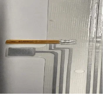
An NTC thermistor is extremely sensitive, so it needs to be encapsulated by a small and highly viscous droplet of resin over it. The resin forms a protective dome for waterproofing and protection from temperature changes and vibration of the external environment.
Step 9. Functional testing
The FDC assembly is checked by a specialized functional testing machine to ensure it works.
Step 10. Packaging
Now the FDC is finished. But it still needs to be ultrasonically welded with a blister or injection molding bracket and copper/aluminum busbars in the later processes. So it is packaged carefully for sending it to the bracket and busbar welding lines.
Conclusion
This guide to flexible die-cutting FDC CCS solution not only introduces what an FDC CCS is and its manufacturing process with details, but also gives an insight into different solutions of CCS, BMS, and battery packs. PCBONLINE provides R&D and manufacturing for the four CCS solutions and BMS, and supplies the busbars, blister/injection molding brackets, nickel sheets, wiring cables, and standard BMS for any CCS/BMS/battery pack projects. If you want to develop your products using an FDC CCS or any other CCS solution, please get in touch with PCBONLINE.
Battery Management System Manufacturing at PCBONLINE.pdf
CCS Product Introduction - PCBONLINE.pdf


