
In a solar energy system, the charge controller, BMS (battery management system), and solar inverter all need to deal with step-down or step-up voltage. Both voltage step up and step down require large currents and lead to a great amount of heat.
How to deal with large current flow and thermal dissipation for the solar inverter, BMS, and charge controller?
You will need high-current PCBAs to conduct the high currents and dissipate heat effectively. In the circuit boards that are responsible for voltage step up or down, if the PCB trace thickness can't be made too large, you will use other methods, such as soldering copper busbars and nickel sheets, to conduct high currents and dissipate thermal.
Below, you can see the high-current PCBAs manufactured by PCBONLINE for BMS, solar inverters, and charge controllers. We are hoping the high-current PCBA examples in this article can help you develop your solder energy products.
In this article:
Part 1: Basics of a Solar Energy System Part 2: High-current PCBAs for Charge Controller, Inverter, and BMS Part 3: Electronic Components Used in the PCBAs of Solar Energy Devices Part 4: PCBONLINE - High-Current PCBA Manufacturer for Solar Energy DevicesBasics of a Solar Energy System
First, let's see an overview of a solar energy system and its devices.
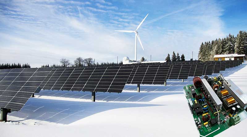
Solar power is a major form of renewable energy, and the world has striven for decades to turn solar power into electricity for home appliances and industrial production. Nowadays, modern solar energy systems can provide stable electricity regardless of the intermittent nature of solar power. Grid-connected photovoltaic (PV) power generation systems can even generate AC (alternating current) municipal power and feed into the public grid.
A modern solar energy system consists of five devices: solar panels, a charge controller, a battery pack, a battery management system (BMS), a solar inverter, and an energy management system (EMS). And they serve the below functions.
Solar panels: The solar panels capture sunlight and convert it into DC (direct current) power.
Charge controller: A charge controller regulates the voltage and current from the solar panels for the battery pack. It consists of several PCBAs, including the main control board, sensor board, power management board (including DC-DC converter and MPPT maximum power point tracking controller), and the interface/display board. It uses data from the BMS to optimize charging.
Battery management system (BMS): The BMS can be considered part of the overall energy management system, but indeed it is an independent device monitoring and managing the cells in the battery pack. It sends a current signal to the NTC (negative temperature coefficient) thermistor on the cell contact system (CCS) of the battery pack, whose resistance varies according to the temperature changes of the cells. The BMS prevents the battery cells from overheating or getting too cold and ensures the cell's consistency in voltage.
Battery pack: A battery pack stores the DC power and outputs stable electricity for home appliances or the public grid. It consists of the CCS and lithium-ion battery cells.
Solar inverter: A solar inverter transforms the DC power from the battery pack into AC electricity for home appliances or feeding into the public grid.
Energy management system (EMS): The EMS manages power generation in the solar panels, energy storage, and power consumption, and it receives data from both the charge controller and the BMS.
As power conversion and voltage step-up/down both require high currents, the solar energy devices require high-current PCBAs (printed circuit board assembly) to connect components and dissipate thermal effectively.
High-current PCBAs for Charge Controller, Inverter, and BMS
As long as the device is related to lithium-ion battery packs and renewable energy, it requires AC/DC conversion and voltage step up and step down. No matter what solar energy device you are developing, such as the solar panel, charge controller, BMS, CCS in the battery pack, solar inverter, or EMS, you may need high-current PCBAs.
High-current PCBA for charge controller
This high-current PCBA for the charge controller is an integrated busbar, which deals with large power and high currents.
For safety and reliability concerns, in the PCB design phase, the electrical networks of large and small currents are separated. The inlaid copper busbars are responsible for high current conduction and thermal dissipation, and the 3oz PCB copper circuits are responsible for small currents and signal transfer.
The effective integration of the FR4 PCB circuits and the copper busbars is critical in the PCB manufacturing process.
When the overall power of the solar energy system reaches 250KVA or above, or when a single charge controller device reaches 100KVA or above, using the integrated busbar PCBA can dramatically increase the performance of the solar energy system.
PCBONLINE has strong manufacturing capabilities and technical experiences in electrical management for such high-current PCBA for renewable energy high-current boards.
Inverter PCBA
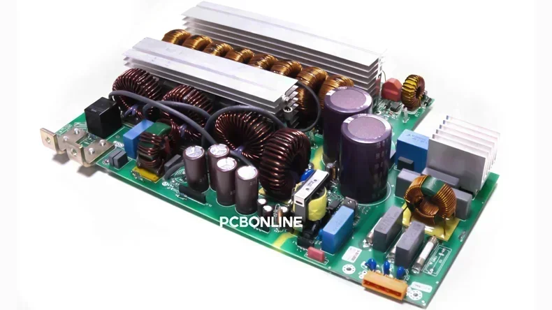
In a solar inverter, both DC-AC current conversion and voltage step-up generate heat. Besides, no inverter is 100% efficient, and there is about 2-5% power lost as heat. For PCBAs of the inverter, thermal dissipation is one of the most important factors.
In the above inverter PCBA, you can see a large area of heat sinks for thermal dissipation. But please also note that all the components on the PCBA are mounted by PTH (through-hole) assembly for better heat conductivity. The large area of PTH assembly requires high solder fullness, sufficient tin intake, and systematic overall thermal dissipation design.
For solar inverter and industrial inverter PCBAs, PCBONLINE pays attention to mold design, temperature control of the wave soldering oven, and PCBA manufacturing flow design. Attention to detail is key to PCBA manufacturing success for high-current inverters.
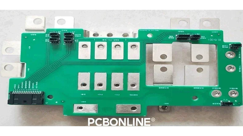
High-Current PCBA for BMS
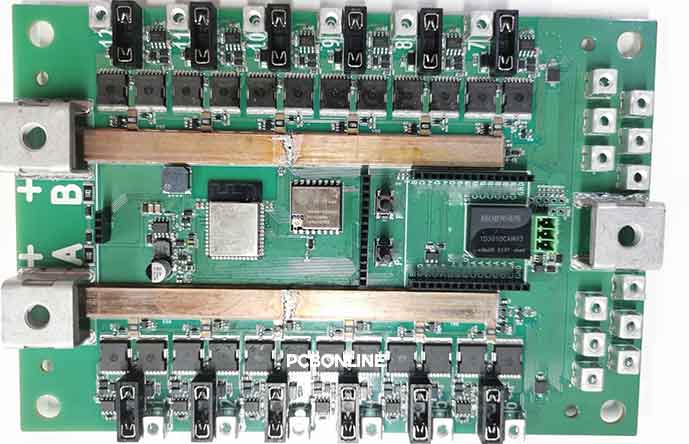
This is a BMS PCBA manufactured by PCBONLINE for a solder energy system. You can see how it prioritizes thermal dissipation and increases the current load in the PCBA design from the terminal blocks and the copper busbars.
In the middle of the high-current PCBA, there are four PCB busbars soldered for sharing currents and increasing current carrying capacity. (when taking a picture of the PCBA, we hadn't sprayed a tin coating on the copper busbars, but we did that later to prevent them from oxidation).
Copper has twice the thermal conductivity of aluminum and the third-best conductivity in metal. Due to its excellent thermal conductivity and current carrying capability, using busbars facilitates thermal dissipation a lot in high-power devices such as the BMS.
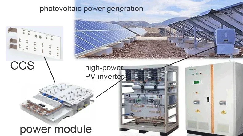
CCS Cell Contact System
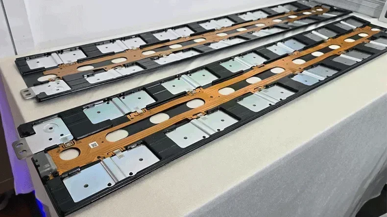
A CCS is used in the battery pack or power bank of the solar energy system. It consists of an FPCA (flexible printed circuit assembly), copper busbars, and insulation structures. When the power bank is at a low level of power, its busbars are the pathway for fast charging. When the power bank has a power of above about 95%, the FPCA is the pathway for slow charging. The BMS controls the CCS.
Large currents flow through the two electrodes (total positive and total negative of the busbars) of the CCS. For this reason, a CCS is a high-current PCBA.
The CCS for the solar energy industry has a lower standard than that for EVs (electric vehicles), but it is higher than that for the energy storage industry. PCBONLINE provides one-stop cell contact system assembly for both EVs and the solar energy industry.
Electronic Components Used in the PCBAs of Solar Energy Devices
The devices in a solar energy system need to withstand high current and control current conversion or manage the charging process. In a solar energy system, these components are used on PCBAs: Microcontrollers (MCUs), sensors, MOSFETs, IGBTs, and diodes.
MCUs
An MCU is a programmable integrated circuit responsible for executing control algorithms, managing communication protocols, and monitoring system parameters. In a solar energy system, MCUs are used in the PCBAs of the charge controller, BMS, solar inverter, and EMS.
MCUs are used in the MPPT controller board of the charge controller device to optimize currents from the solar panels. Besides, the charge controller relies on MCUs to communicate with the BMS to prevent overcharging.
In a solar inverter, the MCU is used to monitor the input and output voltage and current.
In a BMS, there are multiple MCUs for monitoring and managing the cell states and communicating with the charge controller.
Like BMS, the EMS heavily relies on MCUs for monitoring and managing the power generation, storage, and consumption of the entire solar energy system.
MOSFETs and IGBTs
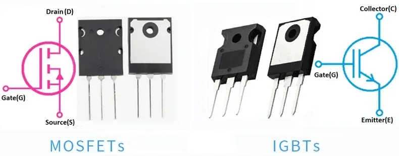
MOSFET and IGBT are both solid-state ICs for voltage control. IGBTs are suitable for the conduction and control of medium to very high currents. MOSFETs are for low to medium currents but are suitable for high-speed switching and amplification.
In a solar energy system, MOSFETs and IGBTs are important components used in the charge controller, BMS, solar inverter, and EMS. They switch rapidly to modulate the DC input from the solar panels into AC output at the desired voltage and frequency.
Sensors
Voltage sensors, current sensors, and temperature sensors are all used in solar energy devices, including the charge controller, solar panel, battery pack, inverter, BMS, and EMS.
In a solar energy system, voltage sensors and current sensors monitor the input and output voltage and currents of each solar energy device to ensure they are within the proper range. Temperature sensors are used to prevent the device itself from overheating.
Diodes
Various diodes are used in solar energy devices, including the solar panel, charge controller, inverter, and EMS.
The PCBA of a solar panel uses blocking diodes to prevent current from flowing back to the panel and bypassing diodes to allow current to bypass shaded or damaged dells to reduce power loss.
The charge controller also uses blocking diodes.
The solar inverter PCBA uses rectifier diodes for AC-DC conversion and freewheeling diodes for the protection of switching components MOSFETs. The EMS uses rectifier diodes and signal diodes.
Besides, the PCBA of the charge controller uses DC-DC converters to step up or down the voltage from the solar panels to charge the lithium battery cells at the normal voltage of 24V/36V/48V. It also uses MPPT controllers to find the maximum power point for power extraction from the solar panels.
What's more, in a solar energy system, the solar inverter has to convert the DC to AC and step up the AC voltage to 110V or 220V. Besides MOSFETs, IGBTs, and MCUs for DC-AC conversion, the inverter PCBA also uses a step-up transformer to increase the AC voltage to the required grid voltage of 111V or 220V.
PCBONLINE - High-Current PCBA Manufacturer for Solar Energy Devices
Not only solar energy devices but also the CCS in EV battery packs, EV inverters, and wind power inverters require high-current PCBAs.
For high-current PCBAs, you can work with the one-stop and cost-effective PCBA manufacturer PCBONLINE. PCBONLINE has two large advanced PCB manufacturing bases, one PCB assembly factory, stable supply chains, and an R&D team to provide you with high-current PCBAs under one roof.
PCBONLINE has strong PCBA manufacturing capabilities and rich technical experiences for devices that require high current carrying and great thermal dissipation, including solar BMS, CCS, PV inverters, industrial inverters, and charge controllers.
PCBONLINE manufactures various high-thermal-conductivity PCBs, including thick-copper PCBs up to 14oz, copper-based PCBs, hybrid-laminated PCBs, ceramic PCBs, etc.
We can inlay and solder copper busbars in various PCBs and solder terminal blocks and optimize trace width/space to increase PCBA current carrying capacity.
In R&D, PCBONLINE excels in thermal dissipation design and electrical management, and we also take care of details in mold design, reflow/wave soldering oven temperature control, and production flow design.
You can have high-current PCBAs for solar energy and EVs manufactured at PCBONLINE from prototypes to batch production, including PCB fabrication, PCB assembly, component sourcing, IC burning-in programming, PCBA value-added, enclosures, and box-build assembly.
We offer free R&D, samples, and PCBA functional testing for high-current PCBA bulk production orders.
High-quality PCBA manufacturing certified with ISO 9001:2015, IATF 16949, RoHS, REACH, UL, and IPC-A-610 Class 2/3.
The PCBA manufacturing process, faculty, time, specs, and all materials are traceable for 15 years for quality traceability.
If you want to get R&D assistance or get a quote for your solder energy devices, PCBONLINE is pleased to receive your message and provide help and PCBA manufacturing services. Please email info@pcbonline.com to reach out to us. We will provide one-on-one engineering support throughout your project.
Conclusion
This article covers the basics of a solder energy system and shows examples of high-current PCBAs for the solar inverter, BMS, and charge controller. High-current carrying capacity and thermal dissipation are crucial for all solar energy devices and applications related to energy conversion and lithium battery energy storage and consumption. PCBONLINE is proud to lead the high-current PCBA manufacturing for renewable energy applications. Contact us to access our PCBA manufacturing services and how we can support your green energy initiatives.
©This article is an original work of the PCBONLINE team. Please indicate the author PCBONLINE if you reprint. If the article is reproduced without permission or indicating the author's source, PCBONLINE reserves the right to investigate the infringement.
Battery Management System Manufacturing at PCBONLINE.pdf
CCS Product Introduction - PCBONLINE.pdf


