
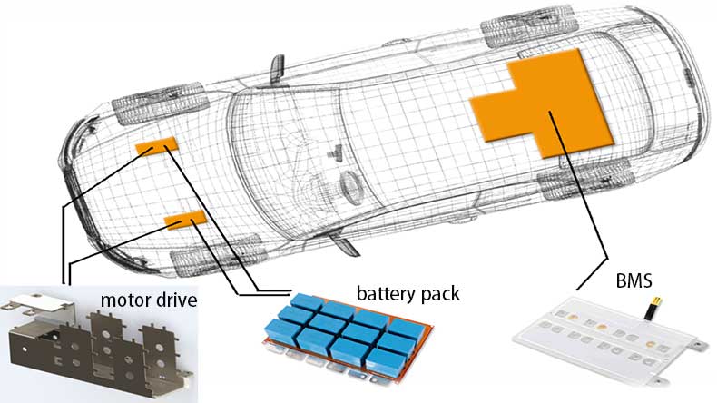
For electric vehicles, the main parts of the driving mechanism of the electric vehicle are Battery Pack, Battery management system (BMS), Controller, and Motor transmission. The BMS monitors the battery cells' status in various aspects and controls the working of the battery pack. For example, it monitors cells' voltage. In this article, we plan to use a simple project to let you understand the basics of how a BMS monitors cell voltage so that you can step forward to design PCBs for lithium-battery packs and EV-related systems.
Lithium-ion Cells vs Lithium Battery Pack vs BMS
First, let's understand the battery pack, cells, and the BMS.
A cell is a single battery. The most common batteries for EVs are lithium-ion batteries. These batteries can be coin-shaped, cylindrical, flat, etc.
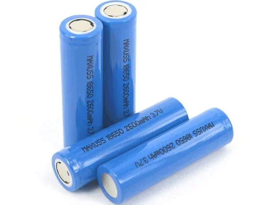
The battery cells are classified by their numbers. For example, 18650 is a common battery dimension number, in which 18 means the battery diameter in millimeters, 65 is the battery length in millimeters, and 0 represents the round shape of the cell.
The voltage of a 18650 normal lithium battery cell is 3.7V, and a 18650 power lithium cell is 3.2V.
The capacity of the cells is in the unit of mAH or AH. For example, the number 2200mAH means this battery cell can provide 2200 milli-amps of current for one hour before it gets discharged.
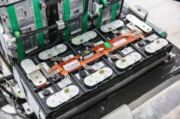
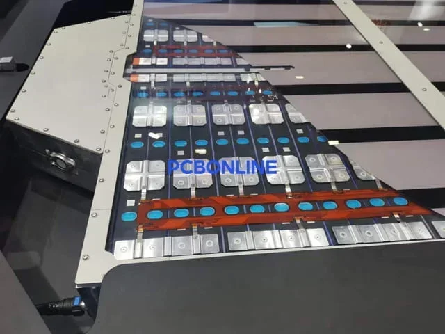
In a battery pack, the cells' electrodes are laser soldered with the busbars of the cell contact system. The connectors of the CCS connect the battery management (BMS). The CCS is also the channel for fast and slow charging.
In an EV, the BMS is separate from the battery pack. It manages the status of the cells, ensures their consistency, and keeps them from being overcharged, under-discharged, and overheating.
The BMS monitors the individual cell voltage of every lithium-ion cell check, checks for its temperature, and monitors the charging and discharging current of the system.
In temperature monitoring, it sends a current signal to the CCS of the battery pack. The resistance of the CCS' NTC thermistors varies as the temperature changes of the cells.
Then, the BMS can analyze the temperature changes of the cells according to the returned current signal from the CCS.
We can briefly summarize that the cells are a part of the battery pack, and the BMS, independent from the battery pack, monitors and controls the status of the cells to ensure battery safety and efficiency.
Basics of Call Voltage Monitoring
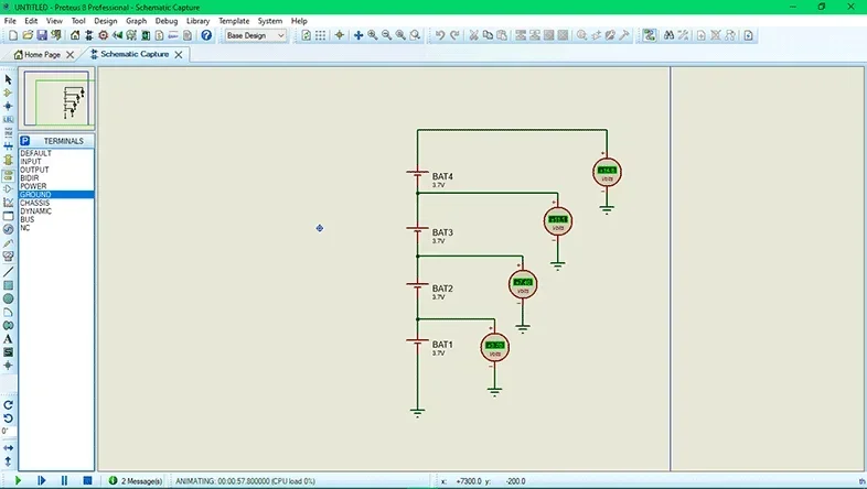
The design of a BMS for an EV is complex. In this article, we will learn how to measure the individual cell voltage from a simple project for easy understanding. It is a four-cell lithium-ion battery pack connected in series to give 14.8V.
In this simple project, the battery cells are not chemically identical. This is for monitoring the testing stage of battery pack assembly, where the cells are not verified to be consistent yet.
Therefore, the combined or total voltage of 6 volts cannot be considered as 3 volts for each cell. The voltage level of individual cells will be different in charging and also when the battery is discharged. For measuring the voltage of the first two cells, the volts of the first cell will be subtracted from the total voltage of the two cells.
For the measurement of a single-cell voltage, a Microcontroller can be used. But for the measurement of different cell voltages individually, we need to introduce some circuits to perform a differential operation. The reference point as the ground remains the same in the measurement of all the cell voltages. For this purpose, we can use a voltage divider circuit. By using the simple voltage or potential divider circuit with the usage of the resistors, the current drawn can be reduced. Therefore, we will be using the op-amp circuit to measure the difference between each cell terminal to find the individual voltage.
Differential op-amp
A simple op-amp has five terminals. The two terminals are for powering the op-amp (8 as Vdd+ and 4 as Vss-). The other two terminals are inverting and non-inverting (pin 2 and 3), and the fifth terminal is (pin 1) output terminal. The description of the pins may vary within different packages.
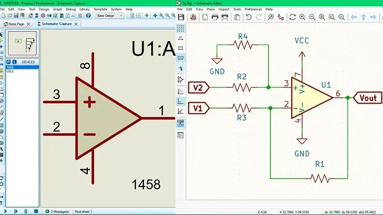
A differential operational amplifier takes the voltage input at two terminals, inverting and non-inverting, compares the voltages to find the difference, and then amplifies. The resulting output can be obtained at the output terminal of the operational amplifier. A basic operational amplifier circuit is shown.
The resistor R1 is acting as a feedback resistor. Although the op-amp can work without this feedback resistor, it will provide high uncontrolled gain, which is practically not useful.
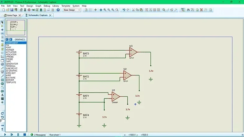
By using the operational amplifier with each single cell, the voltage will be measured individually.
This circuit uses the ideal operational amplifiers, and it is only for representation purposes. For a practical circuit, more components are required for the feedback resistor.
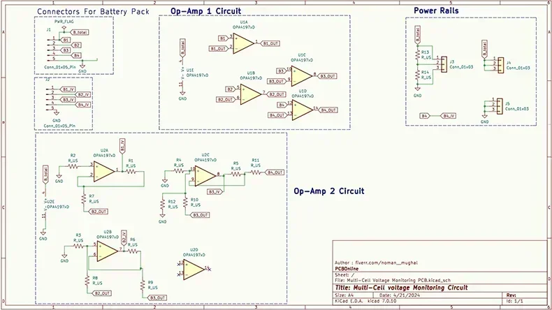
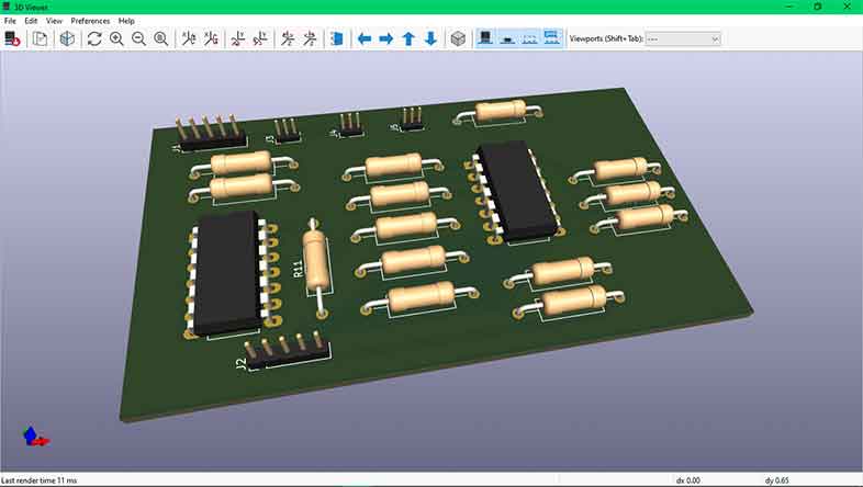
The schematic is designed in kiCAD 7.
As you can see, we have two Quad package rail-to-rail high-voltage op-amp OPA4197 in our circuit, both powered by the total pack voltage. One IC (U1) is used as a buffer circuit, which is also known as a voltage follower, while the other IC (U2) is used to form the differential amplifier circuit. A buffer circuit is required to prevent any of the cells from getting loaded individually, and no current should be consumed from a single cell but only from the pack as a whole. Since the buffer circuit has a very high input impedance, we can read the voltage from the cell without drawing power from it.
All four op-amps in the IC U1 are used to buffer the voltage of the four cells respectively. The input voltages from the cells are labeled from B1+ to B4+, and the buffered output voltage is labeled from B1_Out to B4_Out. This buffered voltage is then sent to the differential amplifier to measure the individual cell voltage, as discussed above. The value of all the resistors is set to 1K since the gain of the differential amplifier is set to unity. You can use any resistor value, but they all should be of the same value, except for the resistors R13 and R14. These two resistors form a potential divider to measure the pack voltage of the battery so that we can compare it with the sum of measured cell voltages.
Rail-to-Rail, high-voltage Op-Amp
The above circuit requires you to use a rail-to-rail high-voltage op-amp like OPA4197. Both the Op-Amp IC operate at the pack voltage that is a maximum of (4.3*4) 17.2V; hence, the Op-amp should be capable of handling high voltages. Also, since we are using a buffer circuit, the output of the buffer should be equal to the pack voltage for the 4th cell terminal, meaning the output voltage should be equal to the operating voltage of the op-amp. Hence, we need to use a rail-to-rail op-amp.
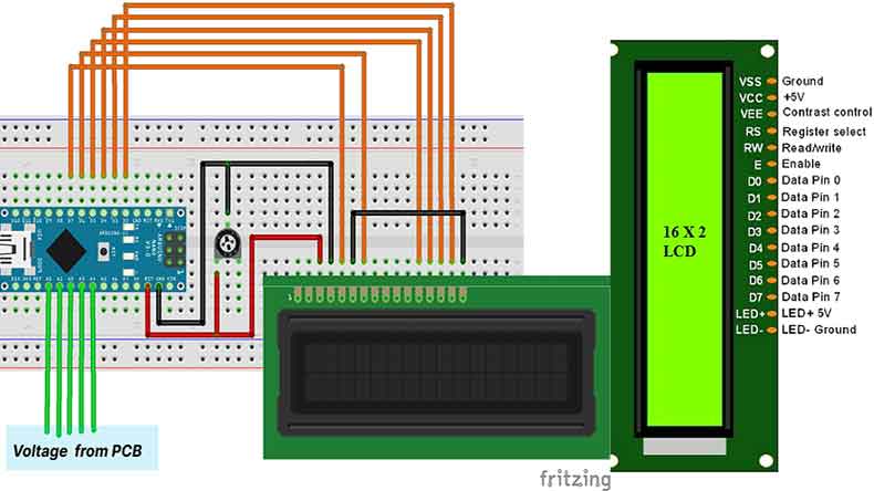
If you cannot find a rail-to-rail op-amp, you can replace the IC with a simple LM324. This IC can handle high voltage but cannot act as a rail-to-rail, so you have to use a pull-up resistor of 10k on the first pin of the U1 Op-Amp IC. The pins description of LCD pins is also shown in the figure below.
In the circuit schematics stage, make the connections of Arduino Nano and the 16x2 LCD to ensure the circuit can work. Connect the output pins from the PCB board to the Arduino's analog pins.
Connect the Arduino to the computer by using the serial port. Select the port and choose the board type. Then, upload the program to the Arduino.
#include
const int rs = 7, en = 6, d4 = 5, d5 = 4, d6 = 3, d7 = 2;
LiquidCrystal lcd(rs, en, d4, d5, d6, d7);
void setup() {
lcd.begin(16, 2);
lcd.print("Voltage Monitor");
lcd.setCursor(0, 1);
lcd.print(" for EV ");
delay(2000);
lcd.clear();
}
void loop() {
float cellVoltage1 = analogRead(A1) * (5.0 / 1023.0);
lcd.print("C1:"); lcd.print(cellVoltage1);
float cellVoltage2 = analogRead(A2) * (5.0 / 1023.0);
lcd.print(" C2:"); lcd.print(cellVoltage2);
lcd.setCursor(0, 1);
float cellVoltage3 = analogRead(A3) * (5.0 / 1023.0);
lcd.print("C3:"); lcd.print(cellVoltage3);
float cellVoltage4 = analogRead(A4) * (5.0 / 1023.0);
lcd.print(" C4:"); lcd.print(cellVoltage4);
delay(4000);
lcd.clear();
float totalVoltage = cellVoltage1 + cellVoltage2 + cellVoltage3 + cellVoltage4;
lcd.print("Total:"); lcd.print(totalVoltage);
lcd.setCursor(0, 1);
float packVoltage = analogRead(A0) * (5.0 / 1023.0) * 4.002;
lcd.print("Measured:"); lcd.print(packVoltage);
delay(2000);
lcd.clear();
}
The voltage of the individual cells will be shown on the LCD.
In the above simple project, you can learn how the voltage of an individual cell in a lithium battery pack is shown in the LCD. The addition of IoT can make further improvements in it. The use of ESP32, ESP8266, or ESP12E will allow us to send the data over the internet and visualize it on the mobile phone or in the LED.
However, a BMS in real use has way more functions than just monitoring the voltages of the cells. What's more, the number of cells in a battery pack is far more than the above simple 4-cell projects.
As the weight of the BMS and battery pack should be as small as possible, and security is of the utmost importance, you may need a professional BMS and CCS manufacturer that can not only manufacture but also design the entire BMS and battery pack for you to ensure consistency of the cells.
BMS and CCS One-Stop Design and Manufacturing from PCBONLINE
You can work with PCBONLINE to have your initial idea of a BMS and Battery pack CCS manufactured into reality. PCBONLINE provides one-stop R&D and manufacturing for custom BMS and lithium battery CCS according to your requirements. We have complete design and manufacturing capabilities to meet your demands.
Quality and security are the most important factors during all the manufacturing processes for BMS, CSS, and the entire battery pack assembly. With the signals collected by the battery pack's CCS, when the BMS detects that the temperature difference between different NTC thermistors on the CCS exceeds the set difference range, it will alarm, and the battery pack will fail the test. This is one of the most tested.
On the PCBAs (printed circuit board assemblies) for the BMS and CCS, we print QR codes for traceability, including all equipment operation specs, faculty, materials of nickel sheets and copper busbars, shearing force, electrical performances, etc.
All the automated optical inspection (AOI) for the PCBA is 3D, which scans all the surfaces of the components, such as NTC thermistors, to ensure the soldering effect and their images have high definition.
Besides traceability, we take care of quality in weight control. We weigh all the PCBAs, CCSes, and BMSes to ensure the consistency of the products.
Comprehensive tests and inspections of the BMS and CCS, including electrical performance testing, salt spray test, immersion water test, short-time high-temperature test, thermal shock, 85℃ constant heat and 85% humidity test, and thermal aging.
With the BMS and battery CCS, you can easily laser solder the battery cells to the CCS, install them into the enclosure, and make the final battery pack. If you haven’t completed the design yet, we suggest you let PCBONLINE do the design for you for the design of BMS and CCS. Feel free to contact the one-stop BMS and CSS manufacturer for EVs by email at info@pcbonline.com.
Reasons to work with PCBONLINE for EV-related PCBA:
PCBONLINE has PCBA and system R&D and manufacturing capabilities for BMS and battery pack's CCS. You can check CCS capabilities from the PDF at the end of the article.
PCBONLINE provides comprehensive development and one-on-one support, including the PCB/FPC, PCBA/system, the entire battery pack, and BMS.
We can provide the entire R&D for the BMS/CCS/battery pack and sample for free for bulk production clients.
Excellent thermal and electrical management. Quality traceability is valid for 15 years.
Besides CCS and BMS, PCBONLINE can also manufacture the motor driving module (inverter PCBA) for you.
Conclusion
A BMS monitors the voltage, power, and temperatures of the lithium battery and controls the charging/discharging and power-off state of the battery pack. It ensures the lithium battery pack works efficiently and securely. This blog uses a simple 4-cell project to help beginners learn how to monitor the voltages of single cells. But it is basic and not available for a real BMS for EVs. The one-stop manufacturer PCBONLINE provides R&D and manufacturing for BMS and battery pack CCS of high quality. If you have any questions about BMS and CSS, feel free to ask us from the online chat window or by email. We will provide one-on-one engineering support.
Battery Management System Manufacturing at PCBONLINE.pdf
CCS Product Introduction - PCBONLINE.pdf


