
Many clients have consulted us about cell connection system specifications and R&D questions, before they can start the initial development for the battery pack. CCS development not only concerns its module, but it is part of the systematic work of the battery pack development. The CCS design must match the battery module arrangement, the cell electrodes' orientations, the pack outline, and the battery management system.
In this guide to the cell connection system, the CCS and custom BMS manufacturer PCBONLINE will walk you through everything about the CCS for developing and prototyping a battery pack.
But wait, before that, you can view what you can deliver to PCBONLINE for the R&D of your cell connection system.
|
CCS module outer dimension data
|
Product performance requirements
|
|
Cell pole & top cover structure matched with the CCS
|
CCS operating current (It determines the material and thickness of the connecting busbars)
|
|
Positioning of the plastic bracket
|
CCS electrical performance requirements (related to material selection)
|
|
Insulation structure of the outputs
|
Number of series and parallel connections
|
|
Size of the outer dimension
|
Cell voltage definition and circuit definition, special requirements, etc.
|
|
Battery cell's laser welding area and laser welding thickness
|
/
|
Here is the specification table of the flexible PCB for the CCS.
|
Specs
|
FPC capabilities
|
|
FPC layer
|
Single-layer/single-layer double contacts/double-layer
|
|
Copper thickness
|
1oz/2oz (minimum 7µm)
|
|
Maximum size
|
Single-layer FPC: 1200mm*230mm
Double-layer FPC: 500mm*230mm |
|
Flex PCB thickness tolerance
|
10%
|
|
Trace width/space
|
Determined by current to flow through, maximum width/space 0.3mm
|
|
Dimensional tolerance
|
<1.5mm
|
|
Auxiliary material fitting tolerance
|
+/-0.2mm
|
|
Surface finish
|
OSP 0.2-0.5um
|
|
Bonding strength between nickel sheet and copper busbar
|
Shearing force>100N, peeling force>25N
|
|
Connector push and pull force
|
≥100N
|
|
FPC upper and lower insulation film withstand voltage
|
a3550VDC, 60s, leakage current ≤1mA
2000VAC, 60s, leakage current ≤2mA |
|
FPC upper and lower insulation film insulation
|
>500MΩ (1000VDC, 60s)
|
|
Loop resistance
|
Single loop internal resistance ≤1Ω
|
|
Working temperature
|
-40℃ to 125℃
|
|
FPC circuit withstand voltage
|
1600VDC, 60S, leakage ≤1mA; 1000VAC, 60S, leakage ≤1mA
|
|
The insulation between FPC circuits
|
>500MΩ (500VDC, 60s)
|
|
Salt spray resistance
|
5% NaCl solution for 96 hours, no effect on appearance and performance
|
|
Flame retardant
|
Complies with UL 94v-0
|
And below are the FDC (flexible die-cutting) CCS specifications at PCBONLINE.
|
FDC capabilities
|
Processing parameters
|
|
Equipment widths
|
250mm
|
|
Processable aluminum thickness
|
0.018mm-0.1mm
|
|
Maximum rotary die diameter
|
400mm
|
|
Minimum line width/spacing
|
0.3mm
|
|
Fuse width
|
Die cutting 0.12mm, laser 0.1mm
|
|
Minimum solder mask opening of the coverlay
|
0.6mm (round hole, square hole)
|
|
Line width processing accuracy
|
±0.03mm
|
|
Cutting seam processing accuracy
|
±0.1mm
|
|
Fitting alignment accuracy
|
±0.2mm
|
|
Outline hole to line processing accuracy
|
±0.2mm
|
|
Minimum spacing from outline edge to board edge
|
2mm
|
|
Thermal lamination roller temperature control
|
Temperature uniformity ±5℃
|
|
FDC appearance
|
Lines are neat and smooth, no jumping edges, no gaps, no copper chips
|
|
Coverlay appearance
|
No bubbles or wrinkles
|
Okay, now let's dive into the overview and manufacturing of the cell connection system!
Overview of Cell Connection System
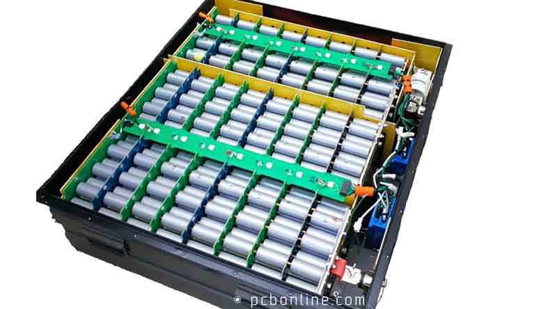
Cell connection systems are used for lithium-ion battery packs for EVs and renewable energy storage and power systems, such as solar and wind energy home storage cabinets.
In a battery pack, the cell connection system is a custom PCBA module connecting the battery cells and the battery management system, providing a path for fast and slow charging and discharging, and collecting voltage and temperature changes for the battery management system.
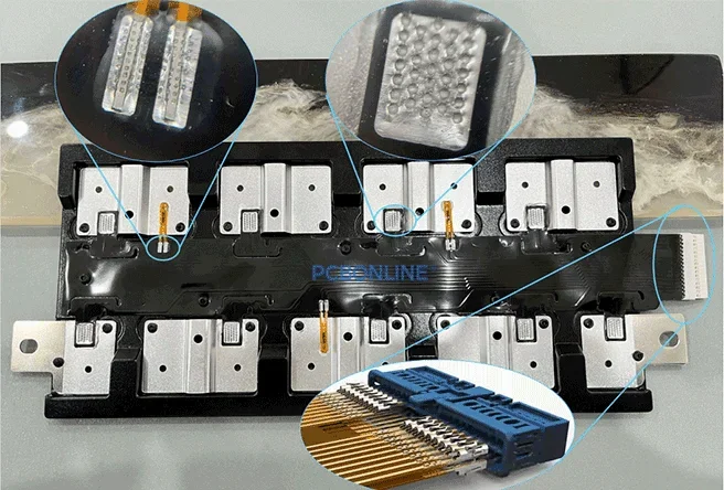
A cell connection system consists of these components:
- The base of the CCS: A flexible PCB (FPC), FR4 PCB, flexible die-cutting (FDC), or wiring cables
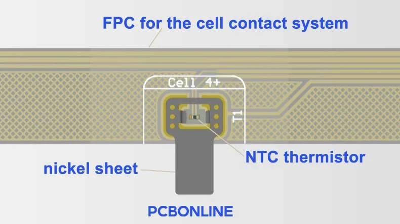
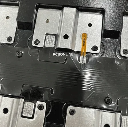
- NTC thermistors: Resistors that act as sensors to detect temperature changes of the battery cells. They are surface mounted on the FPC, PCB, or FDC, or connected with the wiring cable. They are extremely sensitive, so they are encapsulated by a small and highly viscous droplet of resin over them during cell connection system manufacturing.
- Nickel sheets: Customized conductors connecting the FPC/PCB, NTC thermistors, and the battery cells. If the cell connection system uses an FDC or wiring cables, the nickel sheets are not used for the CCS.
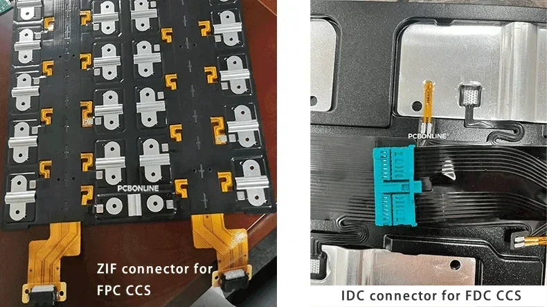
- ZIF or IDC connector: The connector is located at the total current at the beginning or end of the cell connection system. Every CCS has at least one connector. It connects the CCS to the battery pack system. If the cell connection system uses an FPC or PCB as the base, it is a ZIF connector. If it is an FDC CCS, the connector is an IDC (insulation displacement) connector. If the CCS uses wiring cables, multiple ZIF connectors are used.
- Insulation films and blister tray: once the above components are assembled to form the circuit assembly, it is sandwiched with two insulation films and a blister bracket. The insulation films offer electrical insulation between the circuit assembly and the battery cells, and the blister tray supports the assembly.
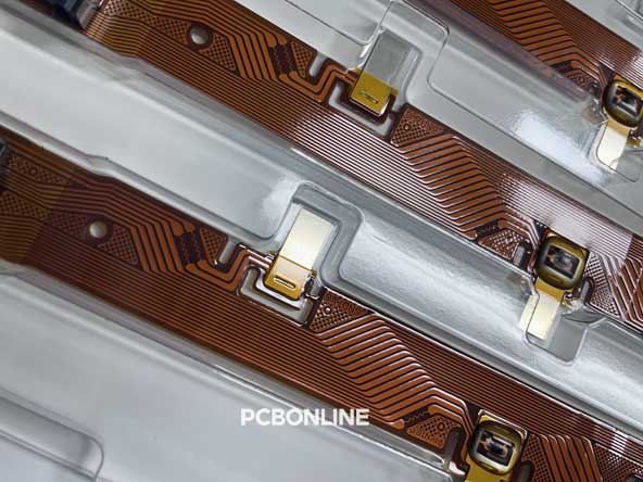
- Copper or aluminum busbars: A busbar connects the circuit assembly of the CCS and the cell electrode. In an FDC cell connection system, the busbar, NTC thermistor, and the FDC base are ultrasonically welded at a point. And the other end of the busbar will be ultrasonically welded with the cell electrode during battery pack assembly.
Types of Cell Connection Systems
Cell connection systems have developed from wiring cables to the flexible and cost-effective FDC types. There are four types of cell connection systems.
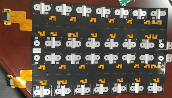
FPC CCS (Flexible Printed Circuit Cell Connection System)
The circuit is etched on the flexible copper foil and polyimide films. Its routing can be very precise, and the CCS can fit in compact spaces.
The NTC thermistors, ZIF connectors, and nickel sheets are surface-mounted on the FPC.
The busbars are laser welded to the other end of the nickel sheets.
The insulation films and the blister tray are thermally laminated on the FPC assembly. Besides, the blister tray or bracket can be laminated to the FPC assembly by thermal riveting.
✅ Pros:
- Compact and lightweight, ideal for EVs, electric motors, and electric boats.
- Flexible PCBs allow for complex wiring and can match complex battery layouts.
- FPC CCS allows a small trace width and provides high precision.
- Have verified its reliability in the market for mass production.
❌ Cons:
- More expensive than other CCS solutions because of several cost items for modelling.
- Complex FPC manufacturing and CCS assembly process.
PCB CCS (Printed Circuit Board Cell Connection System)
The FR4 PCB CCS is rigid. It needs a small amount of wiring harness.
✅ Pros:
- High structural strength and doesn't need a blister tray or bracket for support
- Saves space and weight compared to wiring harness CCS
❌ Cons:
- Rigid and can't adapt to compact spaces that require three-dimensional flexibility
- Compared to FPC or FDC, FR4 PCB is heavier and larger.
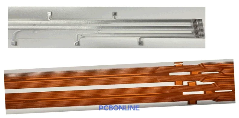
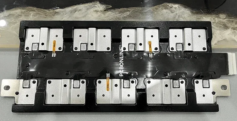
FDC CCS (Flexible Die-Cut Cell Connection System)
The circuit is cut on the PI (polyimide) film and aluminum foil laminated substrate material with rotary dies and/or flat dies.
Its construction is easier than the FPC CCS and requires no nickel sheets.
Besides, all the NTC thermistors, IDC connectors, busbars, insulation films, and blister brackets are ultrasonically welded.
✅ Pros:
- Cost-effective because it needs no modeling and no nickel sheets.
- Provide flexibility and lightweight as FPC CCS does.
- More reliability and quality consistency than FPC CCS because it only requires ultrasonic welding and doesn't cause bubbles.
- Its manufacturing and assembly are environmentally friendly
❌ Cons:
- Low precision because it only allows larger trace width and routing
- It has not been verified for reliability for mass production yet.
Wiring Cables CCS (Wired Harness Cell Connection System)
It uses bulky wire harnesses to connect each cell, NTC, busbar, and several harness cables to a connector. Thus, multiple connectors are required, and the wiring harness cell connection system's size and weight are large.
✅ Pros:
- Its assembly is environmentally friendly
- No modeling cost and cost-effective for small production
❌ Cons:
- Manual assembly is prone to human error and inconsistent quality.
- Heavy and bulky.
- Costly for bulk production due to low automation
Cell Connection System Manufacturing
Let's explore the FPC CCS manufacturing process, which is the most complex.
Part 1: FPC Manufacturing Process
1. Substrate preparation
Material: Polyimide (PI) is most common due to its excellent thermal and electrical properties.
Copper lamination: A thin copper foil (typically 12–35 μm) is laminated onto the polyimide substrate.
2. Circuit patterning
Photoresist application: A light-sensitive film is coated onto the copper surface.
Exposure and development: UV light passes through a circuit mask, exposing the desired pattern.
Etching: Unexposed copper is chemically etched away, leaving the desired trace pattern.
3. Coverlay or Solder Mask Application
A polyimide-based coverlay is laminated over the FPC for insulation and protection, except at the bonding pads or exposed copper areas.
Alternatively, a liquid photoimageable solder mask may be used for tighter tolerances.
4. Surface finishing
Apply ENIG (Electroless Nickel Immersion Gold), OSP, or silver plating to bonding areas to improve solderability and prevent oxidation.
5. Hole drilling/punching
Laser or mechanical drilling creates via holes or slots for mounting, alignment, or cell connection tabs.
6. Die cutting/profile shaping
The FPC is cut to final shape using laser cutting, die punching, or CNC routing.
Part 2: FPC Assembly and CCS Assembly
7. SMT assembly
The FPC is fixed by the FPC SMT assembly jig before going on to the SMT line.
On the specialized SMT line, the FPC is surface mounted and reflow soldered with NTC thermistors, ZIF connectors, and nickel sheets.
8. NTC encapsulation
The NTC sitting in the hollow of the nickel sheet is dosed over with a drop of resin and baked for encapsulation.
9. Thermal lamination
The PET insulation films and blister bracket are thermally laminated to the FPC assembly.
10. Laser welding
Laser-solder the nickel sheets and copper busbars for their connection.
11. functional testing
The FDC assembly is checked by a specialized functional testing machine to ensure it works.
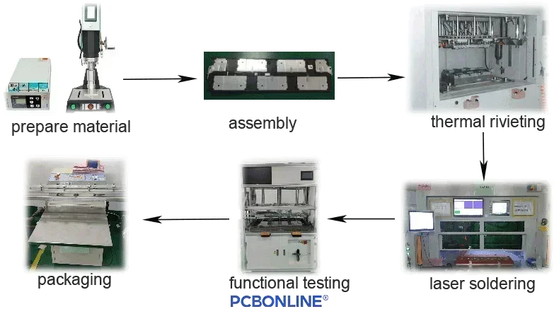
12. packaging.
Regarding the FDC solution, please view the flexible die-cutting and flexible connection manufacturing process.
One-Stop CCS Manufacturer PCBONLINE with R&D Capabilities
PCBONLINE provides turnkey cell connection system manufacturing, including R&D. We have complete equipment specialized for CCS manufacturing and testing. Our experienced engineers can also design the CCS and solve technical issues.
If you haven't completed your battery pack design, including the BMS and the CCS, you can let us design it for you. You can draw the outline of the battery pack and tell us the line connection sequence of the cells and CCS; if possible, send the 3D drawing of the entire pack so that we can understand your CCS and BMS demands.
PCBONLINE provides one-stop manufacturing for FPC, FDC, PCB, and wiring harness cell connection systems.
We take care of CCS manufacturing traceability and print a QR code on the FPC/PCB/integrated busbar PCBA that contains all the information on the manufacturing operations, time, and specs.
Quality is paramount. We focus on weight control to ensure the consistency of all the FPC/PCB/integrated busbars, nickel sheets, NTCs, connectors, insulation films, copper busbars, and a blister tray/plastic bracket.
All the inspections during the FPC/PCB/integrated busbar assembly for the CCS are 3D, including SPI, AOI, and X-ray. The high-accuracy images and dimensions are retained for 5 years for traceability.
We not only provide one-stop manufacturing for the CCS but also can design the CCS and BMS according to your battery pack demands.
We have strong manufacturing capabilities and technical experience in new energy automotive and energy storage electronics, especially thermal and electric management.
We provide one-on-one engineering support and can send a CCS sample to you for free if you plan for bulky production. Please get in touch with us by email at info@pcbonline.com if you have any cell connection system demands.
Conclusion
This guide to cell connection systems covers the overview, their solution types, to CCS manufacturing. PCBONLINE provides R&D and manufacturing for the above four cell connection system solutions and BMS, and supplies the busbars, blister brackets, nickel sheets, wiring cables, and standard BMS for any CCS/BMS/battery pack projects. If you want to develop your CCS or battery pack, please get in touch with PCBONLINE.
Battery Management System Manufacturing at PCBONLINE.pdf
CCS Product Introduction - PCBONLINE.pdf


