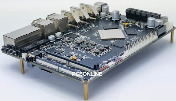
A Microcontroller is an IC (integrated circuit) known as the brain of many embedded systems and electrical gadgets.
This article gives a detailed introduction to Microcontrollers, gives some tips on Microcontroller PCB design, and shows you how to design a Microcontroller PCB.
As there are many Microcontrollers in the market, this article uses 8051 Microcontrollers as an example to illustrate.
If you want to design any Microcontroller product and have a plan for Microcontroller PCB fabrication and assembly, check out the below content.
Part 1: What is a Microcontroller
A Microcontroller, also known as an embedded controller or Microcontroller unit (MCU), is a small integrated circuit that controls a single process in an embedded system.
A typical Microcontroller is a single chip that houses a CPU, memory, and input/output (I/O) peripherals.
Microcontrollers can be programmed to control and manage different operations. In essence, they are basic and tiny personal computers (PCs) without a complicated front-end operating system (OS) that are used to operate smaller components.
Microcontrollers are tasked with handling inputs, carrying out preprogrammed commands, and producing results in electronic systems.
Microcontroller Family
Families of Microcontrollers, sometimes created by the same manufacturer, are collections of Microcontrollers with a similar architecture and instructions.
To retain compatibility with the same development tools and software, each family may contain many Microcontroller models with various features and capabilities.
Following are some prominent Microcontroller families:
PIC (peripheral interface controller)
The PIC Microcontroller series, created by Microchip Technology, is well-known for its vast selection of models and excellent peripheral support. In several embedded applications, PIC Microcontrollers are often employed.
AVR
AVR Microcontrollers are made by Atmel, which is now a division of Microchip Technology, and are renowned for their simplicity and use. In addition to being employed in business applications, they are also used in educational and hobbyist projects.
8051
One of the first Microcontroller families was the 8051 series, created by Intel. It still has some historical applications and has a variety of models.
STM32
The STM32 series was created by STMicroelectronics and is based on the ARM Cortex-M architecture. These Microcontrollers are ideal for a variety of applications, including IoT and industrial automation, thanks to their excellent performance and extensive feature set.
Arduino
Despite not being a single Microcontroller family, Arduino has grown to be a well-liked platform for projects utilizing Microcontrollers. ESP8266/ESP32 and Atmel/Microchip Microcontrollers are used in Arduino boards, which also offer a user-friendly IDE and a wealth of libraries to make programming easier.
Microcontroller Families from Other Manufacturers
Renesas, Silicon Labs, Analog Devices, and Maxim Integrated, among others, all provide Microcontroller families that are specialized for certain purposes.
Besides, the ODM (original design manufacturer) PCBONLINE has self-developed MCU component solutions for civil defense, forest fire prevention, etc.
Main Components of Microcontrollers
Microcontrollers consist of several key components, including:
Central processing unit (CPU): The CPU is the core of the Microcontroller and executes instructions.
Memory: Data memory (RAM) is used for short-term storage on Microcontrollers, whereas program memory (Flash or ROM) stores the program code.
Input/output (I/O) Pins: Through the use of these pins, the Microcontroller may communicate with sensors, peripherals, and other devices outside of it.
Timers and counters: These elements support the generation of precise timing and delays.
Analog-to-digital converter (ADC): It changes analog signals into digital values, such as readings from sensors.
Communication interfaces: For connecting to other devices, Microcontrollers frequently come with UART, SPI, I2C, or other communication interfaces.
Difference between Microcontroller and Microprocessor
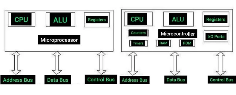
Besides Microcontrollers, you must have considered microprocessors.
The microprocessor has no more components like timer, RAM, ROM, I/O ports, etc.
A Microcontroller has an inside timer, RAM, ROM, I/Os port, etc.
Simply, Microcontroller is a more advanced chip that can connect in different ways.
How do Microcontrollers Work
To control a single device function, a Microcontroller is integrated into a system. It accomplishes this by utilizing its core CPU to evaluate data that it receives from its I/O peripherals.
The Microcontroller receives temporary data stored in its data memory, where the processor accesses it and employs program memory instructions to interpret and apply the incoming data.
It then communicates and takes the necessary action via its I/O peripherals.
Numerous gadgets and systems make use of Microcontrollers. Devices frequently employ several Microcontrollers, which cooperate to carry out the device's many functions.
Part 2: Tips for Designing Microcontroller PCB
To ensure functionality, dependability, and manufacturability, designing a PCB (printed circuit board) for projects based on Microcontrollers demands careful planning and attention to detail.
Start with a clear schematic
Start by drawing a thorough schematic of your circuit that includes every part, connector, and power source. Make certain that your Microcontroller is properly linked to all required peripherals and parts.
Select the right microcontroller
Select a Microcontroller that has the processing speed, memory, and I/O capabilities needed for your project. Think about things like availability and power usage as well.
Component placement
Strategic component placement will reduce signal interference and guarantee effective routing.
For a clearer layout, group together components that are similar.
Follow the manufacturer's instructions and pay attention to how components such as capacitors and diodes should be oriented.
Routing
To prevent crosstalk and avoid crowded places, carefully plan your itinerary. Start by sending high-speed signals.
To reduce signal deterioration, keep traces as short and straight as you can. To lower resistance and enhance power delivery, use thicker traces for power and ground lines.
Design for manufacturing (DFM)
To make your PCB easier to produce, adhere to DFM rules. Maintain appropriate hole diameters, minimum trace widths, and clearances. Make sure your component footprints and packaging match the PCB design by checking them twice.
Testing and debugging
To help with testing and debugging during development and production, include test points for important signals.
For simple visual feedback during testing, take into consideration adding LEDs or other indicators.
Heat management
Provide sufficient thermal relief and take into consideration installing heatsinks or thermal vias if your Microcontroller or other components produce heat.
Documentation
Keep thorough records of your PCB design, such as an assembly layout, a silkscreen layer for component location labels, and a bill of materials (BOM).
Consider EMI/EMC compliance
Design your PCB with shielding, filtering, and appropriate grounding methods if your project must adhere to PCB electromagnetic compatibility (EMC) or electromagnetic interference (EMI) requirements.
Iterate and prototype
Expecting your first PCB design to be flawless is unrealistic. Create a prototype of your PCB and iterate as necessary to fix any problems or make changes.
Review and peer feedback
Have peers or coworkers with PCB design experience assess your PCB design. New eyes can spot design problems.
Use professional design software
To make the design process simpler and guarantee precise layouts, consider purchasing professional PCB design tools like Altium, Eagle, KiCad, or OrCAD.
Learn and stay updated
Learn about PCB design best practices regularly and keep up with the most recent tools and technology.
Below, we select the 8051 Microcontroller as an example for revealing the Microcontroller PCB design.
Part 3: Details of 8051 Microcontroller
An 8051 Microcontroller is an industry-standard Microcontroller noted for its simplicity and adaptability. The PIN diagram and architecture of the 8051 Microcontroller are below.
PIN Diagram of 8051 Microcontroller
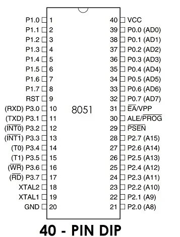
VCC (Pin 40): This pin controls the Microcontroller's supply voltage, which normally needs +5V DC power to function.
GND (Pin 20): This is the ground connection or ground reference.
Port 0 (P0) (Pins 32-39): 8-bit bidirectional I/O port port 0 is available. Each pin may be set up to function as an input or an output separately. When connecting to an external memory, this port also functions as an address/data bus.
Port 1 (P1) (Pins 1-8): Like Port 0, Port 1 is an 8-bit bidirectional I/O port. It may be utilized for external memory interfaces as well.
Port 2 (P2) (Pins 21-28): An 8-bit bidirectional I/O port named Port 2 can be set up as either an input or an output. Additionally, it includes alternative features such as external interrupt inputs.
Port 3 (P3) (Pins 10-17): Another 8-bit bidirectional I/O port with extra features including interrupt inputs and serial communication signals is port 3, which is also an 8-bit port.
RST (Pin 9): This pin serves as a reset input. The high voltage provided to this pin causes the Microcontroller to be reset.
ALE (Address Latch Enable) (Pin 30): For external memory connection, ALE is employed. It shows that throughout memory read/write cycles, the data on the address bus's bottom half is still valid.
PSEN (Program Store Enable) (Pin 29): During program execution, PSEN is utilized to retrieve program code from external memory.
EA (External Access) (Pin 31): To activate or disable external memory interfacing, utilize the EA pin. The Microcontroller downloads code from external memory when EA is high (connected to VCC). It pulls code from internal ROM when EA is low (linked to GND).
XTAL1 and XTAL2 (Pins 18 and 19): The clock signal for the Microcontroller is provided via these pins, which are coupled to an external crystal oscillator or resonator. Although different frequencies may be utilized, 11.0592 MHz is the usual frequency used.
P0.5/T1 (Pin 21): This pin functions as an all-purpose I/O (P0.5) and an external input for Timer 1 (T1).
P0.6/T0 (Pin 22): It functions as a general-purpose I/O (P0.6) and the external input for Timer 0 (T0), similar to Pin 21.
INT0 (Pin 12): This is the input for external interrupt zero.
INT1 (Pin 13): The external interrupt 1 input is this.
TXD (Pin 11): For UART communication, this is the serial data send output.
RXD (Pin 10): This is the input for serial data received by the UART.
8051 Microcontroller Architecture
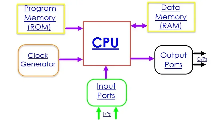
The Harvard design of the 8051 microcontroller which contains separate ROM and RAM for programs and data, makes it an 8-bit Microcontroller.
The main elements and characteristics of its architecture are as follows.
Central Processing Unit (CPU)
The CPU of the 8051 is an 8-bit processor in charge of carrying out software commands. It features several internal registers, including the Program Counter (PC), B register, and Accumulator (ACC).
Memory
Program memory (ROM): The firmware or program code is kept in the program memory of the 8051. Standard 8051 models normally have it at 4 KB (4096 bytes) in size.
Data memory (RAM): During program execution, temporary data are stored in the data memory. Normally, it is 128 bytes in size.
Registers
Accumulator (ACC): The main accumulator for arithmetic and logic operations is the ACC register.
B register: Another multipurpose register is the B register.
Data pointer (DPTR): A 16-bit register called DPTR is used to access places in external memory.
Program counter (PC): The address of the following instruction to be executed is stored in the PC register.
Stack pointer (SP): When calling and returning from subroutines, the stack is managed by the SP register.
Input/output (I/O) ports
The 8051 normally has four parallel I/O ports with eight pins each (P0, P1, P2, and P3). These ports include input and output configuration options.
You may interface with external memory via P0 and P2.
Timers and counters
Two 16-bit timers/counters are available on the 8051: Timer 0 and Timer 1. These clocks are employed for jobs that need accurate timing intervals and time management.
Serial communication
The universal asynchronous receiver/transmitter (UART) on the 8051 allows for serial connection with external devices. It enables the transmission and receipt of serial data.
Interrupts
Both hardware and software interrupts are supported by the 8051.
There are five interrupt sources: a serial communication interrupt (UART), two external interrupts (INT0 and INT1), two timer interrupts (0 and 1), and two timers (0 and 1).
Clock source
To supply a clock signal, the 8051 needs an external crystal oscillator or resonator. Although various frequencies may be utilized, 11.0592 MHz is a frequently used frequency.
Control and status registers
The Microcontroller's actions are controlled by some control and status registers, including those used to configure interrupt priority, establish timer modes, and set I/O pin configurations.
Part 4: Components of 8051 Microcontroller PCB
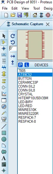
Here is the list of electronic components that can be used for drawing the 8051 Microcontroller-based testing PCB circuits. In the PCB design, you can select components from the list.
The 8051 Microcontroller PCB components' functions and details are below.
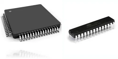
8051 Microcontroller
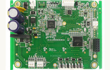
An 8051 Microcontroller, which acts as the brains of your projects, sits in the center of the PCB board. It can communicate with external components and run programming that is stored in its memory.
Power Supply
The voltage regulators and filtering components in the power supply circuit ensure a steady and sterile power source for the Microcontroller and peripherals. To meet their needs, users can input a broad variety of voltages.
User Interface
The user interface of the 8051 Microcontroller PCB includes LED indicators, push buttons, and an LED display.
Connectivity
Timing
Programming
The 8051 Microcontroller may be immediately loaded with new code via the board's programming interface.
Part 5: Microcontroller PCB Design Process Step-by-Step
Below, we create a versatile and small electrical testing platform called the 8051-based Mini-testing board.
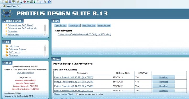
Step1. Open Software and create a new project
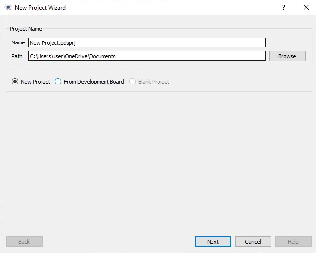
Step 2. Create the project name and save it.
Step 3. Then select the component that one needs.
Step 4. When we select the component, we draw a circuit.
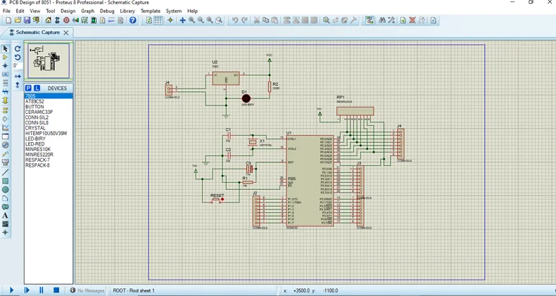
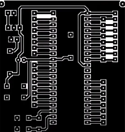
Step 5. When the schematic diagram is ready, we connect the PCB layout.
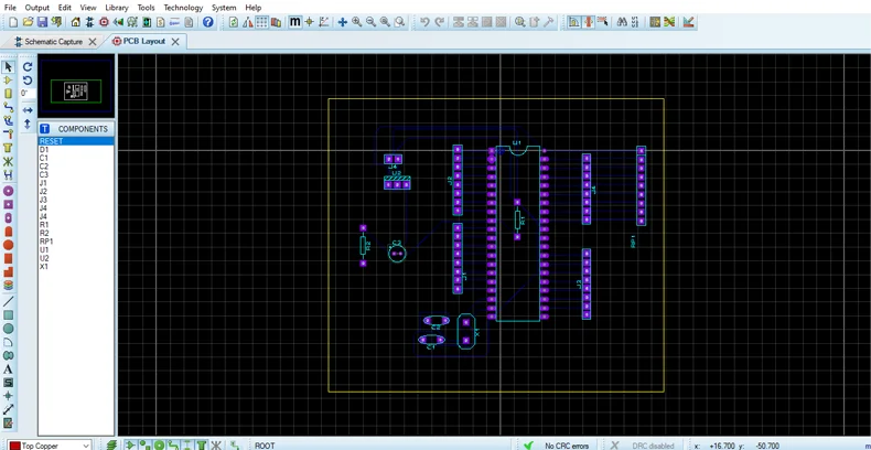
Step 6. Then export the PCB design in a PDF format.
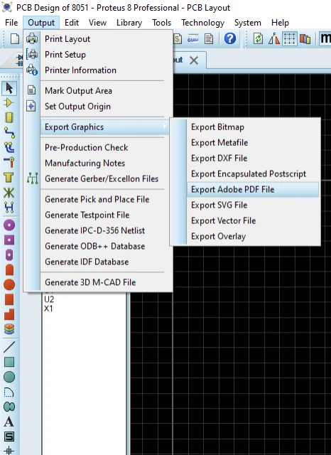
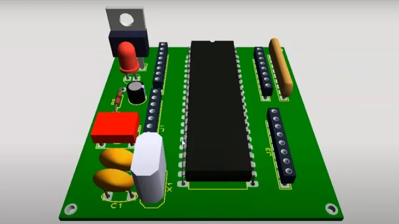
Step 7. Have the 3D visualization process and check the 3D assembly.
Part 6: Applications of Microcontroller PCB
Microcontrollers are adaptable to a variety of devices, including vending machines, office equipment, robotics, cars, medical devices, and office machines.
Microcontroller PCBs find applications including:
Automotive: In infotainment, airbag systems, engine control, and other areas.
Consumer electronics: In-home electronics, remote controls, and intelligent gadgets.
Industrial control: In industries and industry, for automation and process control.
Medical devices: In the equipment for healthcare monitoring and control systems.
Home automation: For smart home systems and IoT devices.
Aerospace and defense: In navigation, armament systems, and avionics.
Part 7: One-Stop R&D and Microcontroller PCB Manufacturer PCBONLINE
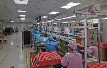
PCBONLINE is an EMS (electronic manufacturing services) provider for Microcontroller PCBs, assemblies, and finished products.
Founded in 1999, PCBONLINE has a professional R&D team, two large advanced PCB manufacturing bases, and one EMS PCB assembly factory.
PCBONLINE provides flexible production for Microcontroller PCB. If you do not have a Microcontroller PCB design, PCBONLINE can design it for you. If you are an original equipment manufacturer with design, PCBONLINE can also provide one-on-one engineering support all the way.
PCBONLINE provides turnkey contract manufacturing services to make your initial idea into reality and take care of quality-related issues after selling.
The R&D team of PCBONLINE has rich experience and expertise in Microcontroller PCB design and DFM (design for manufacturing).
PCBONLINE provides cost-effective Microcontroller PCB fabrication and assembly as it is a source factory manufacturer.
Relying on its EMS PCBA factory, PCBONLINE can source original Microcontrollers of any type at a lower price.
PCBONLINE secures every IC is real, new, and original and provides a free counterfeit test for every Microcontroller.
If you order high-volume PCB assembly, PCBONLINE can charge free for the design of a Microcontroller PCB project.
The Microcontroller PCB manufacturing and assembly at PCBONLINE are certified with ISO 9001:2015, IATF 16949, REACH, RoHS, UL, and IPC
Are you ready for Microcontroller PCB manufacturing, PCB assembly, or box-build assembly? Contact the one-stop Microcontroller PCB provider PCBONLINE by email at info@pcbonline.com.
Conclusion
A Microcontroller is the brain of embedded systems and sits in the center of the Microcontroller PCB. This article introduces what a Microcontroller is, lists the families of Microcontrollers, takes the 8051 Microcontroller as an example to explain the component's PIN diagram and architecture, gives tips on Microcontroller PCB design, and finally, shows the Microcontroller PCB design process. If you need Microcontroller PCB fabrication and assembly, work with the affordable one-stop manufacturer PCBONLINE.
PCB assembly at PCBONLINE.pdf