

The rapid evolution of New Energy Vehicles and stationary energy storage systems has placed the Cell Contact System (CCS)) at the forefront of battery safety and performance.
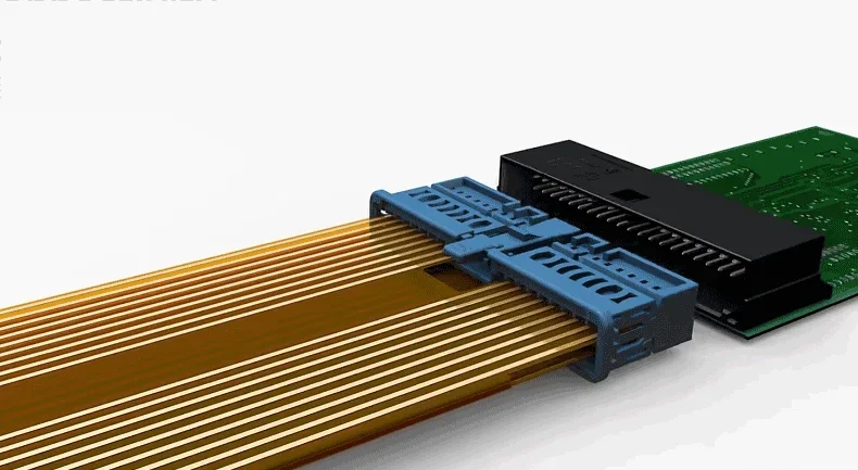
As a critical component integrating signal collection (via FPC, PCB, or FFC), plastic structural parts, and busbars (copper or aluminum), the CCS facilitates high-voltage series-parallel connections while monitoring cell temperature and voltage. To ensure long-term reliability and safety, rigorous testing across integrated, automotive, and energy storage domains is mandatory.
PCBONLINE is a one-stop CCS manufacturer providing end-to-end solutions from flexible PCB to CCS module design and welding. Our guide explores the CCS testing protocols and standards, including EV power battery CCS and energy storage system CCS.
In this article:
Part 1: CCS Integrated Testing Protocols Part 2: Power Battery CCS Testing Standards Part 3: Energy Storage Battery CCS Technical Specifications Part 4: CCS Technology: Current Status and Future Trends1. CCS Integrated Testing Protocols
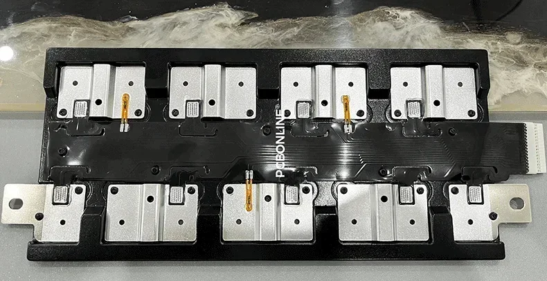
Integrated testing assesses the CCS assembly as a whole, ensuring that individual components like the FPC and busbars function harmoniously after assembly processes such as laser welding and hot riveting.
Routine Inspection and Dimensional Accuracy
- Visual inspection: The assembly must be free of surface defects such as cracks, burrs, or delamination. The busbar carrier's warpage must be ≤2mm.
- Welding quality: Laser weld points must show no signs of burning through, cracks, or "ghosting." Nickel terminals should remain undeformed.
- Dimensional checks: All components must meet specific blueprint requirements to ensure a perfect fit within the battery module.
- Connector integrity: Pin alignment must be precise, with a maximum tilt degree of ≤ 50% of the PIN thickness.
- Mechanical fastening: Hot-riveted "mushroom heads" must meet specific height and clearance requirements to prevent component detachment.
Functional and Mechanical Performance
- Connector durability: Low-voltage connectors must withstand ≥ 20 insertion/extraction cycles. Post-test requirements include zero pin misalignment and a loop resistance increase of ≤ 20%.
- Welding strength: The horizontal pull force between the nickel tab and busbar must be ≥300N, with a peel force ≥40N.
- Insulation and voltage resistance: Assemblies must pass a 1000VDC insulation resistance test (≥1000MΩ) and a 3000VDC voltage endurance test with leakage current <0.1mA.
Environmental Durability
- Vibration testing: Conducted according to ISO 16750-3, monitoring continuity and temperature sensor resistance during the process.
- Thermal shock and cycling: Ensuring that the integrated assembly maintains its structural and electrical integrity across extreme temperature fluctuations.
2. Power Battery CCS Testing Standards
Power battery applications, particularly for electric vehicles, demand high reliability under harsh mechanical and environmental conditions.
Power battery CCS components are governed by rigorous automotive standards, such as T/EJCCCSE, designed to ensure safety in high-performance electric vehicles.
Material and Mechanical Requirements
- Standards compliance: Assessments follow GB/T 1040.1 for plastic tensile properties and GB/T 4340.1 for metal Vickers hardness.
- Thermal resilience: Components must withstand high-temperature endurance tests at 175℃ for 6 hours without degradation.
Specialized FPC Environmental Testing
- Salt spray resistance: FPCs must pass tests defined by GB/T 2423.17 to ensure corrosion resistance in coastal or high-humidity areas.
- Winding test: After 4 hours at -40℃, the FPC is wound around a 2.1mm axis with a 0.5kg weight. No cracking is permitted.
- Impact test: Conducted per GB/T 28046.4-2011 to ensure the FPC does not fracture under sudden mechanical shock in cold climates.
3. Energy Storage Battery CCS Technical Specifications
For Energy Storage Systems (ESS), the CCS prioritizes long-cycle life and stable monitoring under high-voltage conditions, often following T/CASMES XXX-2024.
Design and Safety Principles
- Core objectives: CCS design for ESS must prioritize personnel safety, high reliability to minimize maintenance, and full compatibility with diverse battery system components.
- Structural strength: The assembly must possess sufficient mechanical rigidity to withstand the vibrations and impacts associated with shipping and stationary installation.
- Component reliability: Includes NTC (Negative Temperature Coefficient) thermistor verification to ensure accurate thermal monitoring for the BMS.
Durability and Aging Tests
- High temperature and humidity: Samples are aged at 85°C and 85% RH for 1000 hours. Success is defined by line resistance changes <10% and no visible degradation like plating peeling or pin loosening.
- Salt spray resistance: Components must survive 72 hours of continuous salt spray (5% NaCl solution) without corrosion affecting functionality. Plated busbars must meet protection levels defined in GB/T 6461-2002.
- Mechanical thrust test: Specifically for nickel tab pads, requiring a horizontal thrust force ≥80N to ensure robust connection to the FPC.
4. CCS Technology: Current Status and Future Trends
The industry is moving toward high-integration models that reduce the number of cables and potential failure points, thereby increasing energy density and system efficiency. Current technology excels in high-current environments and thermal management through optimized structure and materials.
Future Strategic Trends
- Intelligent monitoring: Integration of advanced communication protocols (CAN, Modbus) and smart sensors for remote monitoring and real-time safety data.
- Lightweighting & cost optimization: Transitioning from traditional FPCs to more cost-effective alternatives like Flexible Die-cutting Circuits (FDC) or Flexible Laser-cutting Circuits (FLC).
- Global standardization: Establishing a unified framework across ISO, IEC, and national standards (GB/T) to ensure product interchangeability and safety in the global market.
One-Stop CCS Manufacturer PCBONLINE
PCBONLINE provides end-to-end CCS design, manufacturing, and assembly services. We have complete equipment specialized for CCS manufacturing and testing. Our experienced engineers can also design the CCS and solve technical issues.
If you haven't completed your battery pack design, including the BMS and the CCS, you can let us design for you. You can draw the outline of the battery pack and tell us the line connection sequence of the cells and CCS; if possible, send the 3D drawing of the entire pack so that we can understand your CCS and BMS demands.
Our expertise is currently focused on:
- Energy Storage CCS: Robust designs for large-scale and residential ESS.
- Light Electric Vehicles: Tailored solutions for two- and three-wheelers.
- Low-Speed Electric Vehicles: Specialized systems for golf carts and similar utility vehicles.
We take care of CCS manufacturing traceability and print a QR code on the FPC/PCB/integrated busbar PCBA that contains all the information on the manufacturing operations, time, and specs.
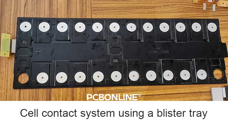
Quality is paramount. We focus on weight control to ensure the consistency of all the FPC/PCB/integrated busbars, nickel sheets, NTCs, connectors, insulation films, copper busbars, and blister tray/plastic bracket.
All the inspections during the FPC/PCB/integrated busbar assembly for the CCS are 3D, including SPI, AOI, and X-ray. The high-accuracy images and dimensions are retained for 15 years for traceability.
We not only provide one-stop manufacturing for the CCS but also can design the CCS and BMS according to your battery pack demands.
We have strong manufacturing capabilities and technical experience in new energy automotive and energy storage electronics, especially thermal and electric management.
We are committed to quality, offering a 5-year quality guarantee on our CCS products, ensuring your battery systems remain safe and efficient for years to come. Please get in touch with us by email at info@pcbonline.com if you have any CCS demands.
Conclusion
This comprehensive guide provides a deep dive into the technical standards and testing protocols for Cell Contact Systems (CCS) used in power batteries and energy storage systems. If you want to develop your products using a cell contact system, please get in touch with PCBONLINE.
Battery Management System Manufacturing at PCBONLINE.pdf
CCS Product Introduction - PCBONLINE.pdf


