
Polyimide (PI) circuit boards are the base of flexible electronic devices. Polyimide flexible printed circuit boards (FPCs) can connect circuits and carry components in compact spaces and offer flexibility and reliability. They are vital for applications where FR4 and other rigid PCBs cannot perform. PCBONLINE manufactures and assembles polyimide circuit boards at one stop. In this article, we will illustrate why polyimide is the preferred material for flexible PCBs and detail manufacturing, assembly, and advantages of polyimide circuit boards.
Content in this article:
Polyimide: The Foundation of Flexible Circuits Polyimide Flexible PCBs Rigid-Flex PCBs Using Polyester Polyimide vs. Polyester: A Comparison Advantages of Polyimide in Circuit Boards Disadvantages of Polyimide in Circuit Boards Polyimide Circuit Board Manufacturing at PCBONLINE PI Flexible Circuit Board Assembly by PCBONLINE Polyimide Circuit Board Copper Types The Structure of Polyimide Circuit Boards Partner with PCBONLINE for Polyimide Circuit BoardsPolyimide: The Foundation of Flexible Circuits
Flexible PCBs, also called flex printed circuits or FPCs, are designed to bend and fit in compact and dynamic electronic devices. They save weight and space. Polyimide is the primary material providing flexibility in the flexible PCB.
In a flexible circuit board, polyimide serves multiple crucial roles:
- It acts as the substrate. It provides the base layer for the circuit.
- Polyimide functions as the insulation material. It prevents electrical shorts between circuit layers.
- PI is used as the coverlay material. The coverlay protects the internal of the FPC, including the circuit traces, from environmental damage and mechanical stress.
Flexible PCBs usually use the polyimide material. However, transparent flexible PCBs are an exception, which use polyester (PET) material instead, meeting specific aesthetic or optical requirements.
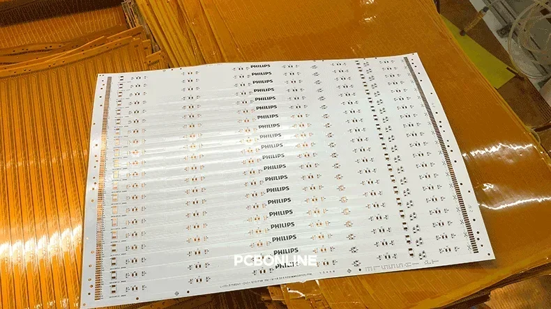
Polyimide Flexible PCBs
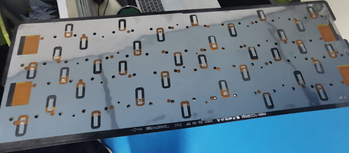
A polyimide flexible circuit board uses polyimide (PI) as its core material. PI provides both the substrate and the insulation for the electronic components and traces.
Polyimide FPCs can bend, twist, and conform to various shapes. They are ideal for compact designs and applications where space is limited or where movement is required. They are significantly lighter and thinner than FR4 PCBs, making them perfect for miniaturized electronics.
Polyimide's properties include high heat resistance, chemical stability, and excellent electrical insulation, contributing to the robust performance of the flexible circuits. They are widely used across diverse industries, including consumer electronics, automotive, medical devices, and aerospace, due to their reliability and versatility in dynamic environments.
You can see what PCBONLINE can do in polyimide flexible PCBs:
|
Features
|
Polyimide FPC Parameters
|
|
Layers
|
1 to 8 (Rigid-flex PCBs 2 to 24 layers)
|
|
Copper thickness
|
Common thicknesses include 12μm, 18μm, 35μm, 70μm, and 105μm.
|
|
PI thickness
|
12.5μm, 25μm, 50μm, and 75μm
|
|
Adhesive thickness
|
Typically 20μm
|
|
Minimum PI FPC thickness
|
Can be as thin as 2.36mm
|
|
Surface finish
|
ENIG, OSP, immersion tin, immersion silver, and hard gold plating
|
|
Minimum trace width/space
|
1.6mil/1.6mil
|
|
FPC stiffeners
|
Polyimide, FR4, and stainless steel
|
Rigid-Flex PCBs Using Polyimide
Rigid-flex PCBs also rely on polyimide material. They have the outer FR4 PCB layers, but their inner layers are entirely a polyimide flexible circuit board. So, a rigid-flex PCB is essentially a polyimide flexible PCB.
Rigid-flex PCBs do not use polyester because they demand higher durability - only polyimide can offer both flexibility and durability. Compared with polyimide, polyester lacks the robust mechanical and thermal properties.
While polyimide is synonymous with flexible and rigid-flex circuits, its use in rigid circuit boards is very rare. This article focuses primarily on polyimide's role in flexible and rigid-flex applications, where its properties are most impactful and utilized.
Polyimide vs. Polyester: A Comparison
The choice between polyimide (PI) and polyester (PET) for flexible PCBs depends on application-specific needs. Both polyimide FPCs and polyester FPCs offer flexibility, but their properties are greatly different.
- Polyimide offers superior thermal resistance. It withstands much higher temperatures than polyester. This makes polyimide ideal for applications requiring standard reflow soldering temperatures.
- Polyimide FPCs also have greater mechanical strength and durability. PI is ideal for flexible electronic applications requiring repeated bending or operating in harsh conditions.
- Also, PI's excellent dielectric properties ensure reliable signal integrity, which is vital for high-performance electronics.
PET flexible PCBs are transparent flex circuit boards. They are made from polyester material and flexible copper foil. PET serves as the base, insulation, and coverlay. The copper foil is laminated onto the PET film. It is then etched to form circuit traces. PET flex PCBs typically have 1 to 6 circuit layers. They offer transparency, light weight, and bio-safety. They are also recyclable.
A major limitation of PET flexible PCBs is their low-temperature resistance. All flexible circuit boards require reflow soldering for component attachment. PET flexible PCBs must be reflow soldered at temperatures below 120°C. This restricts their use in high-temperature environments or with certain components.
|
Features
|
Polyimide flex PCB
|
Polyester flex PCB
|
|
Transparency
|
Not transparent
|
Transparent
|
|
Reflow temperature resistance
|
Below 300°C
|
Below 150°C
|
|
Working temperature resistance
|
Around 200°C
|
Below 80°C
|
|
Durability
|
Superior mechanical strength and durability
|
Can't be bent much or will break
|
|
Applications
|
PI is for high-performance, high-temperature, and demanding flex and rigid-flex applications.
|
PET is suited for low-cost, low-temperature, transparent applications.
|
Advantages of Polyimide in Circuit Boards
Polyimide is advantageous for flexible circuit boards due to its properties.
- Exceptional flexibility: PI material allows circuits to bend, twist, and fold without damage. This enables innovative product designs.
- High thermal resistance: Polyimide can withstand extreme temperatures. This makes it suitable for demanding industrial and automotive applications. It handles the heat generated during operation and assembly processes.
- Excellent electrical insulation: PI provides superb dielectric strength. It minimizes signal loss. It ensures reliable electrical performance.
- Chemical resistance: Polyimide is resistant to many chemicals. This enhances board longevity. It protects circuits in harsh environments.
- Mechanical stability: PI maintains its structural integrity under stress. It offers high tensile strength. This ensures long-term reliability.
- Lightweight and thin: PI enables the creation of very thin and light circuits. This is crucial for miniaturization. It is essential for portable devices.
Disadvantages of Polyimide in Circuit Boards
Despite its many benefits, polyimide has some drawbacks.
Higher cost: PI material and its processing are generally more expensive than other materials. This can increase the overall cost of the PCB.
Moisture absorption: Polyimide can absorb moisture. This may affect its electrical properties in humid conditions. Proper sealing or coatings can mitigate this.
Assembly challenges: Flexible polyimide circuit boards require careful handling during assembly. Their flexibility makes them prone to movement. So, flexible circuit board assembly requires using fixtures during the whole assembly process. PCBONLINE addresses this challenge effectively by custom designing the fixtures to securely hold the flexible circuits during assembly. This ensures precise component placement and soldering.
Polyimide Circuit Board Manufacturing at PCBONLINE
PCBONLINE offers comprehensive polyimide circuit board manufacturing services. Our process ensures high-quality and reliable flexible PCBs.
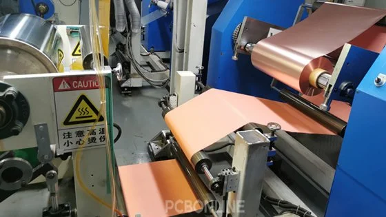
The manufacturing process begins with fabricating flexible PCB laminates. These consist of rolled annealed (RA) or electro-deposited (ED) copper foil, polyimide, and adhesive.
Next, the coverlay and copper foil are laminated.
Laser drilling creates through-holes (PTH).
Vacuum copper plating (VCP) ensures uniform copper thickness.
Circuit transfer uses UV-sensitive photoresist.
Etching removes unwanted copper. This leaves precise circuit traces and pads.
Positioning holes are drilled.
An electrical test verifies connectivity.
The boards undergo cleaning and scrubbing.
FPC layers are aligned and laminated.
Silkscreen printing adds markings.
Baking cures the materials.
Surface finishing protects exposed copper pads.
A final electrical test is performed.
The PCBs are then profiled (cut).
Visual inspection ensures quality.
Sampling testing provides further quality control.
Finally, boards are packaged and prepared for shipping.
Except visual inspection, all the other above steps are machine-operated, guided by our CAM engineers. For detailed insights into the manufacturing process, refer to PCBONLINE's comprehensive guide on Flexible PCB Manufacturing Process.
PI Flexible Circuit Board Assembly by PCBONLINE
As we mentioned, flexible PCBs' bendable nature makes them susceptible to movement during SMT (Surface Mount Technology) assembly, so we custom-design the assembly fixtures and have them manufactured for assembly. The FPC assembly process at PCBONLINE includes:
- Optional baking: PCBs are baked if stored for a prolonged period to remove any absorbed moisture.
- Crucial fixation with fixtures: Flexible PCBs are securely held in place using custom-made jigs. These jigs prevent movement during solder paste printing and component placement. They are custom-made based on the PCB's size, positioning holes, and SMD locations. PCBONLINE provides various jigs: a base, a padded board (magnetic or non-magnetic), and a steel sheet (for magnetic pads). Magnetic padded boards are efficient for bulk orders. Non-magnetic pads with high-temperature tape suit smaller quantities.
- Solder paste printing and component placement: Automated machines apply solder paste and place components accurately.
- Reflow and dual-AOI inspection: The polyimide flexible PCBAs are preheated and soaked to solder the components tightly on the FPC, and then cooled down and removed from the reflow oven. Both before and after reflow soldering, the PCBAs are inspected with an on-line AOI machine to ensure assembly quality.
- Optional thermal lamination: This step integrates flexible circuits into modules.
Besides manufacturing and assembly, PCBONLINE performs comprehensive testing on polyimide flexible PCBs. These tests include tension testing, button strike life testing, bending testing, hand sweat testing, pull strength tests of solder joints, environmental protection tests, metallographic microscope inspection, bridge testing, fuse testing, and salt spray tests. Our rigorous testing ensures the highest quality and reliability of flexible circuit board assemblies.
Polyimide Circuit Board Copper Types
Understanding the material parameters is crucial for designing and manufacturing polyimide circuit boards.
The types of flex PI copper clad laminates (CCL) that PCBONLINE uses include TaiFlex adhesive FCCL, adhesiveless DFCCL, low-loss FCCL, and halogen-free, high-Tg, anti-migration, and low-loss coverlays and bonding sheets. Specific materials like DuPont Kapton (B, CRC, EN, FN, HN, MT, PRN, PST, etc.) and Shengyi (SF490, SF280, SF201, SF305, etc.) are used.
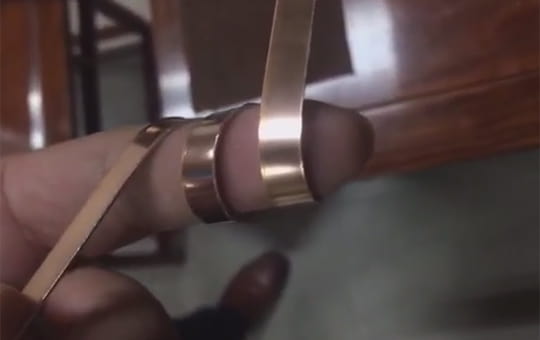
Both rolled annealed (RA) copper and electro-deposited (ED) copper foils are used in flexible PCBs. The choice depends on the application's bending requirements.
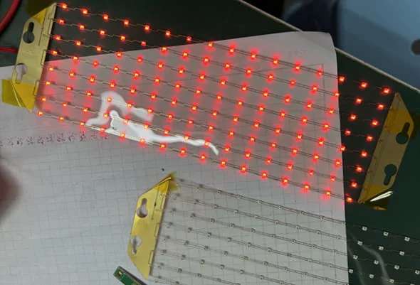
RA copper is preferred for flexible PCBs undergoing repeated bending. Examples include slider phone boards, foldable LED screens, and certain medical devices. RA copper has a layered crystal structure. It offers excellent extensibility (20% to 45%). However, its rough surface can make fine circuit etching challenging. If RA copper is used, an adhesive is required to bond the conductor and insulating layers, which increases the overall thickness.
ED copper is typically used for flexible PCBs operating in a static state. Applications include lighting, batteries, and car taillights. ED copper usually does not require adhesive, resulting in a thinner FPC. It has a pillar crystal structure. Its extensibility is less than RA copper (4% to 11%). However, its fine surface is beneficial for etching fine circuit traces. Advances in manufacturing, like thermal treatments, are improving ED copper's flexibility.
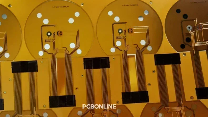
The Structure of Polyimide Circuit Boards
A polyimide circuit board consists of the following parts.
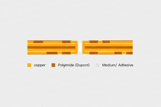
- Substrate: This is the base polyimide film. It provides mechanical support and electrical insulation.
- Copper conductor layers: These are the etched copper traces that form the electrical circuits. They are laminated onto the polyimide substrate.
- Adhesive layer (optional): Some flexible PCBs use an adhesive layer to bond the copper to the polyimide substrate. Adhesiveless laminates are also available, offering thinner and more flexible designs.
- Coverlay: This is an outer protective layer, typically made of polyimide. It covers and protects the circuit traces from environmental factors, moisture, and physical damage.
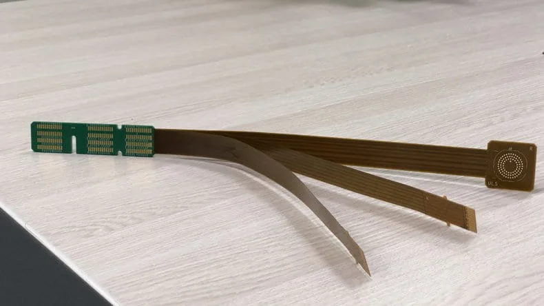
- Stiffeners (optional): These are rigid materials (PI, FR4, or stainless steel) added to specific areas of the flexible circuit. They provide mechanical support for components or connectors, enhancing overall rigidity in selected regions while maintaining flexibility elsewhere.
Partner with PCBONLINE for Polyimide Circuit Boards
If you're looking for polyimide circuit boards, work with the one-stop FPC manufacturer PCBONLINE, who is ready to help. Founded in 2005, PCBONLINE has an FCCL factory, an FPC manufacturing, and an FPC assembly factory, stable supply chains, and an R&D team.
PCBONLINE has turnkey polyimide circuit board fabrication and assembly capabilities. It not only fabricates and assembles FPCs, but also provides FCCLs custom-made for FPC fabrication.
Not only polyimide flexible circuit boards, PCBONLINE also manufactures polyester flexible circuit boards and polyimide rigid PCBs.
Powerful FPC manufacturing capabilities, including 1 to 8-layer PI FPCs with the maximum length of 200m, HDI, and rigid-flex FPCs.
PCBONLINE provides free DFM (design for manufacturing) and one-on-one engineering support for FPC projects, including PCB optimization.
Affordable FPC manufacturing and assembly, as we are an FPC source factory manufacturer who can also fabricate the FCCLs.
High-quality FPCs certified with ISO 9001:2015, ISO 14001:2015, IATF 16949:2016, RoHS, REACH, UL, and IPC-A-610 Class 2/3.
The professional team at PCBONLINE ensures high-quality FPCs and assembly tailored to your project's custom requirements. To get a quote for your polyimide circuit board project, please contact info@pcbonline.com.
Conclusion
Polyimide circuit boards are indispensable for flexible electronics. Their superior flexibility, high thermal resistance, and robust electrical properties make them the material of choice for demanding applications. To manufacture flexible electronic products with reliability at reasonable costs, work with the one-stop FPC manufacturer PCBONLINE.


