
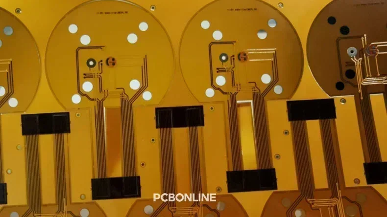
3-layer FPCs with silver plating + carbon ink smile face pads manufactured by PCBONLINE
Choosing the flexible printed circuit board (FPC) or flexible die-cutting (FDC) circuit to connect and support components in your flexible electronic project? The advanced circuit manufacturer, PCBONLINE, provides two prominent flexible options: Etched FPC and FDC, and answers what situations to use them in. Explore etched FPC and FDC in our article easily.
What is Etched FPC?
An Etched Flexible Printed Circuit (FPC) is a flexible printed circuit board. It is made of polyimide (PI) or polyester (PET) laminated with flexible copper clad laminate (FCCL) foils etched to create the fine circuits. Etched FPCs can range from 1 to 8 circuit layers and allow for significant bending and folding. FPCs conduct electrical current and transmit signals. They offer high reliability and 3D circuitry in compact spaces.
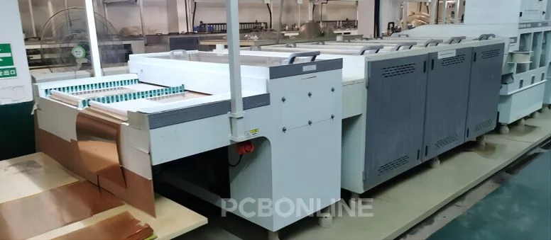
The etching process in FPC manufacturing
The circuits embedded between the thin and flexible sheets allow surface-mounted components (SMDs) to be integrated into a small area. Chemical etching and vertical continuous plating (VCP) are the most important steps in the FPC fabrication process. During etching, unprotected copper areas are dissolved, leaving only the desired circuit traces and pads. Surface finishes, like immersion gold (ENIG), are applied to the copper pads.
FPCs are lightweight and small. They are easy to install in complex spaces. Their flexibility makes them ideal for various applications, such as flexible LED strips, camera modules, fingerprint modules, battery packs, etc.
Etched FPC vs FDC
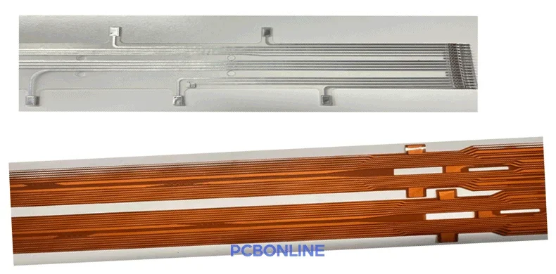
FDC flexible die-cutting circuit
Flexible Die-Cutting (FDC) circuits can be an alternative to etched FPCs for single-layer circuits that don't require fineness. An FDC circuit is made of PI laminated with aluminum foil, mechanically cut by dies. FDCs can bend, fold, twist, and stretch.
A notable application is the FDC Cell Connection System (CCS). At PCBONLINE, our FDC CCS system uses IDC (insulation displacement) connectors. It also incorporates ultrasonically welded NTC (negative temperature coefficient) thermistors, insulation films, blister brackets, and aluminum/copper busbars to form the final FDC CCS.
Here is a comparison between etched FPC and FDC:
Circuit complexity and fineness: Our FPCs can be multilayer up to 8 layers and support very fine circuits with the smallest trace width/space of 1.6mil. This is because its circuit is created by exposure, development, and then etching. However, FDC can only be single-layer, and can't support fine traces and small widths.
Manufacturing complexity: FDC has less manufacturing complexity. It does not require SMT soldering, thermal lamination, or laser welding. Fitting IDC connectors is simpler. Ultrasonic welding is also more straightforward. FPC involves more intricate processes than FPC.
Manufacturing costs: FDC offers significant cost savings. Its manufacturing costs can be about one-third of FPC. This is due to the less complex manufacturing process. Besides, custom jigs or fixtures are not required during prototyping for FDC.
Quality reliability: Etched FPC has proved high reliability over decades in both prototyping and mass production for high-end applications like automotive and medical electronics. Though the manufacturing and assembly process of flexible PCBs involves more steps than FDC, comprehensive testing and inspections at PCBONLINE ensure high quality. FDC has not proved its reliability for high-performance applications in mass production yet.
Environmental friendliness: FDC manufacturing is environmentally friendly. It uses mechanical die cutting and bypasses corrosive substances used in PCB and FPC manufacturing. FPC production involves chemical etching processes.
Here's a brief comparison table between etched FPC and FDC.
|
Feature
|
Etched FPC
|
FDC
|
|
Circuit layer
|
1 to 8 layers
|
only 1 layer
|
|
Circuit complexity
|
fine and complex circuits with small width
|
simple circuits with a large width
|
|
Circuit creation method
|
etching and VCP plating
|
mechanically cut by dies
|
|
Circuit assembly method
|
SMT surface mount technology
|
ultrasonic welding
|
|
Manufacturing eco-friendliness
|
Etching is not eco-friendly.
|
Its entire manufacturing process is eco-friendly.
|
|
Manufacturing cost
|
high for prototyping, but cost-effective for mass production
|
cost-effective for both prototype and mass production
|
|
Market verification
|
Yes, it has been verified in the past decades.
|
Not yet
|
|
Length
|
Both support toll-to-toll production. Our maximum length is regularly 100m, and the limit is 200m.
|
|
While FPC is currently the mainstream solution, FDC CCS is emerging. Though the FPC manufacturing process is complex and its etching is not environmentally friendly, FPC is highly reliable. FDC is still undergoing market verification.
Etched FPC Manufacturing Process at PCBONLINE
The manufacturing of Etched Flexible Printed Circuits (FPCs) is a multi-step, precision-intensive process at PCBONLINE. It ensures the creation of highly reliable and flexible circuits.
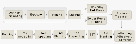
Here is a detailed breakdown of our key stages:
1. Material preparation:
The process begins with the core material. This is typically a copper-clad polyimide (PI) film. This film serves as the substrate. It provides flexibility and a base for the circuitry.
2. Cleaning:
The copper surface must be perfectly clean. Contaminants can cause defects. Industrial cleaning machines are used to remove dust, oil, and oxides. This prepares the surface for photoresist application.
3. Photoresist lamination/coating:
A critical layer is applied next. This is a photosensitive material called photoresist. It can be a liquid coating or a dry film. The photoresist adheres to the copper surface. It will define the circuit pattern.
4. Exposure/imaging:
The circuit design is transferred onto the photoresist. This is done using a photolithography process. A film or digital mask is used. It contains the precise circuit image. UV light passes through this mask. The light cures or hardens specific areas of the photoresist. These hardened areas will protect the copper traces.
5. Developing:
The exposed panel moves to a developing solution. This solution washes away the unexposed photoresist. The areas that were protected by the mask remain. The copper beneath the cured photoresist is now exposed. This forms the desired circuit pattern outline.
6. Etching:
This is the core etching step. The panels enter an etching line. This etching line is long and modular. An etching solution is sprayed onto the panels. This solution usually contains a NaOH mixture. It chemically dissolves the exposed, unprotected copper. The copper areas covered by the cured photoresist are resistant. They remain intact, forming the circuit traces and pads. PCBONLINE achieves fine control here. They ensure precise trace widths and spaces.
7. Stripping:
After etching, the remaining cured photoresist is removed. This step is called stripping. A stripping solution dissolves the hardened photoresist. This leaves only the bare copper circuit traces on the polyimide film. The circuit is now clearly defined.
8. Punching/drilling:
Holes are then created in the FPC. These holes are for component mounting or connections. PCBONLINE uses various drilling methods. Mechanical drilling creates precise holes. For complex shapes or smaller holes, laser drilling is utilized. Laser drilling can produce square or rectangular pads. This offers more design flexibility.
9. Surface finish:
A protective surface finish is applied. This prevents copper oxidation. It also prepares surfaces for soldering. Immersion Gold (ENIG) is a common finish for FPCs. It provides excellent solderability and corrosion resistance.
10. Coverlay/lamination:
A coverlay layer is applied over the circuit. This is usually a thin polyimide film with adhesive. It protects the copper traces from environmental damage. It also provides insulation. For multi-layer FPCs, lamination processes bond layers together.
11. Electrical testing:
Each FPC undergoes rigorous electrical testing. This includes open/short circuit tests. It ensures circuit integrity and functionality. Automated Optical Inspection (AOI) also verifies design accuracy.
12. Profiling/cutting:
Finally, the FPCs are cut to their final shape. This is done using precision profiling equipment. It can involve punching, routing, or laser cutting. This separates individual FPCs from the larger panel.
PCBONLINE's commitment to precision at each stage ensures high-quality Etched FPCs. We meet the strict requirements of modern electronics.
Select Etched FPC or FDC?
The choice between Etched FPC and FDC depends on your project requirements. Each solution offers different advantages.
Choose Etched FPC when:
- High-density and complex circuits are needed: FPCs excel in intricate designs. They support very fine lines and spaces. This allows for high component density for advanced electronics.
- Established reliability is paramount: FPC technology is mature and widely adopted. It has a proven track record and is a reliable choice for critical applications such as automotive, medical, and communications applications.
- Specific component integration is required: FPCs are suitable for Surface Mount Technology (SMT). They can accommodate various components, including fine-pitch ICs.
- Applications demand extreme flexibility and durability: FPCs are designed for repeated flexing. They maintain integrity in dynamic environments. This is ideal for wearables or robotics.
- High performance in signal transmission is key: FPCs offer excellent signal integrity. They are suitable for high-speed data applications.
Choose FDC when:
- Cost reduction is a primary concern: FDC offers significant cost savings. This is due to its simpler manufacturing and fewer materials, such as stiffeners, are needed.
- Simplified assembly is desired: FDC avoids complex soldering processes. It uses IDC connections and ultrasonic welding. This streamlines assembly.
- Environmental impact is a major consideration: FDC is an eco-friendlier circuit option. Its manufacturing bypasses chemical etching and has almost no hazardous waste.
- The application allows for single-layer circuits: FDCs are only single-layer. They are best suited for designs with fewer components and large-space circuit traces.
- Proof of concept or market verification is underway: FDC is still a new technology. It is still gaining market acceptance and can be a good choice for innovative projects.
PCBONLINE's Etched FPC Manufacturing and Assembly Services
For high-quality flexible circuit solutions, consider working with PCBONLINE. Founded in 2005, PCBONLINE has an FCCL factory, an FPC manufacturing, an FPC assembly factory, stable supply chains, and an R&D team. We provide comprehensive Etched FPC manufacturing services. If you want custom-made FDCs, we can also supply them to you.
No matter what flexible circuit solutions you are looking for, FDC, FPC, rigid-flex, transparent circuits, or wiring cables, you can work with the flexible circuit manufacturer PCBONLINE for R&D and one-stop manufacturing.
PCBONLINE has turnkey FPC fabrication and assembly capabilities. We not only fabricate and assemble FPCs but also provide FCCL.
Powerful FPC manufacturing capabilities, including transparent PET FPC, 1 to 8-layer PI FPCs with a maximum length of 200m, HDI, and rigid-flex FPCs.
Our FPC fabrication includes the FCCL fabrication, so we can reduce the FPC manufacturing price.
PCBONLINE provides free DFM (design for manufacturing) and one-on-one engineering support for FPC projects, ensuring optimal performance and reliability.
PCBONLINE does comprehensive tests, such as ensuring the bend radius, the tension test, the bending test, the button strike life test, the hand sweat test, the environmental protection test, the metallographic microscope inspection, the bridge test, etc.
High-quality FPCs certified with ISO 9001:2015, ISO 14001:2015, IATF 16949:2016, RoHS, REACH, UL, and IPC-A-610 Class 2/3.
We ensure precision in every step, including the etching process, in FPC manufacturing and assembly. To get a quote for your etched FPC project or if you want any FDC solution, please contact info@pcbonline.com.
Conclusion
FPCs are etched flexible circuit boards whose copper thickness is achieved by VCP plating, and their circuit can be complex and multilayer. While FPCs are mechanically cut by dies and their circuits are simple, reliability is still being verified by the market. If you want to develop your products using any FPC or FDC, PCBONLINE can provide turnkey electronics manufacturing for you.
Flex PCB cell contact system fabrication at PCBONLINE.pdf


