
FPC is short for flexible printed circuit board. An FPC is also known as a flexible PCB, which can be used for all electronic devices that require flexibility and compact spaces. In this article, you can learn about what an FPC is, tips for designing the pads of an FPC, the flexible printed circuit manufacturing process, and whether to use coverlay or print solder mask for your FPC.
In this article:
Part 1. What is an FPC? Part 2. Tips in PCB Pad Design of Flexible Printed Circuits Part 3. Flexible Printed Circuit Fabrication Process Part 4. Use Coverlay or Print Solder Masks for FPC? One-stop FPC Manufacturer PCBONLINE Meeting All Custom Design RequirementsWhat is an FPC?
An FPC or flexible printed circuit is a PI (polyimide) or PET (polyester)-based flexible printed circuit board with high reliability and excellent flexibility.
By etching the FCCL (flexible copper-clad laminate) on the thin and bendable plastic film, the FPC can mount many components in a compact space to form a flexible circuit.
Flexible printed circuits can bend and fold, with light weight, small size, good heat dissipation, and easy installation.
Besides accommodating components, the FPC itself conducts current and transmits signals.
The structure of an FPC consists of the FCCL, copper layers, insulation layers, and the coverlay.
FCCL: The substrate is composed of the PI/PET, adhesive, and copper foil. Width 250±2 mm or 500±2 mm, length 50±1 mm or 100±1 mm per roll.
Copper layers: The conductive layers for circuit connection. Use RA (rolled annealed) copper for frequent-bending FPC and ED (electrolytic deposited) copper for static-use FPC. Copper thicknesses include 12um, 18um, 25um, and 35um.
Adhesive: Modified epoxy thermosetting adhesive for attaching the PI/PET film to copper. An FPC can also be adhesive-free, which has better flexibility than those with adhesive.
Coverlay: It is equivalent to the solder mask of the PCB to protect the top and bottom copper layers from short circuits, oxidation, moisture, and dust. It is composed of a PI/PET layer, an adhesive layer, and a release paper. An FPC can also use a solder mask that is silkscreen printed on the FPC rather than the coverlay. The last part of this article will explain whether to use coverlay or solder masks for the FPC.
Stiffener: Stiffeners can provide support and strength for plugging the FPC in connectors. FR4 stiffeners thickness 0.1mm to 2.0mm. PI stiffener thickness 0.025mm to 0.2mm. Steel stiffener thickness is 0.15mm to 0.3mm.
Double-sided tape: It provides high-strength bonds to the narrow and smooth surfaces of the FPC.
EMI shielding film: It is laminated after coverlay laminating on the FPC when the signal lines are on the top layer of the board. It prevents signal distortion caused by electromagnetic interference.
Metal domes: They are installed on the button pads of the FPC for switching and controlling between the operator and the product. Their actuation forces include 130gf, 160gf, 250gf, and 280gf. Their thickness is 0.05mm to 0.1mm.
Surface finishes: The common surface finishes of flexible printed circuits are immersion gold (Ni 1μm to 4μm, Au > 0.2μm) and OSP. Besides, the surface finishes for an FPC include plating tin, immersion tin, HASL, and electroplated Ni-Au.
PCB Pads and Related Designs of Flexible Printed Circuits
In the design of a flexible printed circuit board, the PCB pad and its related designs are important.
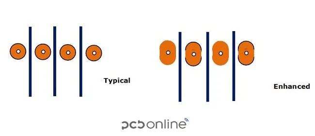
In an FPC, the PCB pads are usually designed to be oval or rounded rectangular pads. In FPC layout optimization, it is common to optimize the rounded pads into an oval or a rounded rectangle. Why?
Here are two reasons:
First, oval and rounded rectangle pads provide more resistance against stress concentration and offer more soldering reliability. They reduce the risks of FPC bending point cracks and meet the pad design recommendations in IPC-7351.
Second, unlike solder masks that are silkscreen printed, the coverlay of an FPC is thermally laminated on the FPC and mechanically drilled, so rectangular pads will be made into rounded rectangles pads in manufacturing.
However, at the flexible PCB manufacturer PCBONLINE, besides mechanical drilling, die pressing is also available, which can make the coverlayer opening in a square or rectangular shape as the design.
So, how to design the pads of an FPC?
The regular design process is:
First, design the original pad, which is rounded or rectangular. Second, design the solder mask opening that allows soldering. Third, generate the corresponding STM stencil opening.
To avoid stress concentration and increase solderability, when you do the packaging or run the DRC, manually or automatically stretch the rounded pad to be oval, for example, a 1mm rounded pad to be a 1.4mm x 1mm oval pad. Or you can use a rounded rectangle with a corner radius of 0.25mm.
For a high-reliability FPC, design the PCB pads in the structure below:
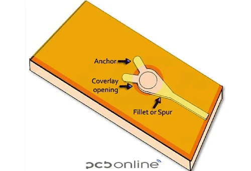
The anchor provides mechanical reinforcement to prevent the pad from falling off. It is important for the FPC area that is hot-pressed during flexible PCB assembly or repeatedly plugged in use.
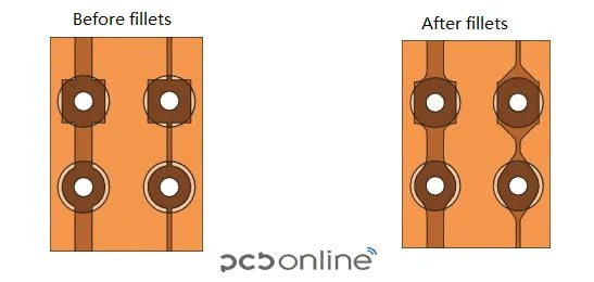
The fillet provides solderability and enables the visual inspection for quality control. It forms around the component lead.
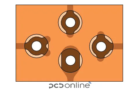
Besides the pads, design a hold-down tab around the SMT solder joints. It is an extended structure that enhances pad fixation and prevents peeling and lifting. It is used at the pad edges with the coverlay or stiffener.
Flexible Printed Circuit Fabrication Process
The Flexible printed circuit fabrication process is shown below. Please note that there are two ways to make the protective layer of the PCB: hot pressing coverlay and silkscreen printing solder masks. In the next part, we will talk about whether to use coverlay or solder masks.
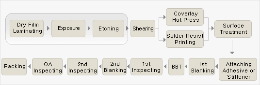
Note: BBT is bare-board testing.
In the 14 steps of flexible printed circuit fabrication, the critical steps are attaching and hot pressing the coverlay and die pressing the coverlay to create the square or rectangular pad.
First, regarding attaching the coverlay, it requires manual alignment to attach. Why?
Unlike rigid PCBs, FPCs have expansion and contraction in the coverlay, and machines cannot grasp their expansion and contraction coefficient, so the PCB industry still uses manual alignment to paste the cover film.
The technicians at PCBONLINE's FPC factory are very skilled with an average experience of 5+ years. This job has high technical requirements.
Second, regarding hot pressing or thermal laminating the coverlay onto the FPC, the lamination temperature is 180℃±10℃. It includes two stages: pre-pressing for 10 seconds with a pressure of 30 kg, and forming for 60 seconds with a pressure of 130 kg.
Third, regarding die pressing or punching the coverlay, it requires a custom mold. If there's no custom jig, die pressing is unavailable, and the square or rectangle pads will be mechanically drilled to be oval or rounded, or rectangle-shaped.
Our precious blog about flexible printed circuit board manufacturing reveals the FPC fabrication process in detailed text, step by step. If you want to explore more details about FPC fabrication, you can read the previous blog.
Use Coverlay or Print Solder Masks for FPC?
To put it first, our answer is to use double-sided coverlay as much as possible.
An FPC using a coverlay is more flexible, reliable, stable, and durable. The disadvantage is that it requires a mold to punch the coverlay to make a square or rectangular pad, which increases the FPC fabrication costs. It is suitable for mass production and long-term stable return orders.
Solder mask printing is silkscreen printing a 10um-thick liquid PCB ink on the flexible printed circuit and then heat-curing to adhere it to the circuit after baking. The advantage of solder mask printing is that you don't need to buy a custom mold. However, its disadvantage is that the PCB ink is easy to crack. After repeated use of the FPC, the ink will crack or even fall off, failing to protect the circuit, and is not durable or stable. It is only suitable for fixed working environments without bending.
So our final answer is that, unless your FPC is used for static applications without any bending, use coverlay.
One-stop FPC Manufacturer PCBONLINE Meeting All Custom Design Requirements
If you're looking for flexible printed circuit R&D and one-stop electronics manufacturing, work with the EMS (electronics manufacturing service) FPC manufacturer PCBONLINE, who is ready to help. Founded in 1999, PCBONLINE has an FCCL factory, an FPC manufacturing, and an FPC assembly factory, stable supply chains, and an R&D team.
PCBONLINE has turnkey FPC fabrication and assembly capabilities. It not only fabricates and assembles FPCs, but also provides FCCLs custom-made for FPC fabrication.
PCBONLINE has FPC project R&D capabilities and can do the FPC design or take part in your project's development from the early stage.
Powerful FPC manufacturing capabilities, including transparent PET FPC, 1 to 8-layer PI FPCs with a maximum length of 200m, HDI, and rigid-flex FPCs.
PCBONLINE provides free DFM (design for manufacturing) and one-on-one engineering support for FPC projects, including FPC layout optimization.
PCBONLINE does comprehensive tests, such as ensuring the bend radius, the tension test, the bending test, the button strike life test, the hand sweat test, the environmental protection test, metallographic microscope inspection, the bridge test, etc.
High-quality FPCs certified with ISO 9001:2015, ISO 14001:2015, IATF 16949:2016, RoHS, REACH, UL, and IPC-A-610 Class 2/3.
The professional team at PCBONLINE specializes in creating high-quality FPCs and assembly tailored to your project's custom requirements. To get a quote for your FPC project, please contact info@pcbonline.com.
Conclusion
Proper pad and related design and advanced fabrication are important for flexible printed circuits to avoid cracks and lower fabrication costs. To design and manufacture FPCs with reliability at reasonable costs, work with the one-stop FPC manufacturer PCBONLINE.


