
Measuring PCB copper thickness in ounces (oz) has been a PCB industry convention for decades. PCB copper thickness in oz means that the weight of PCB copper traces evenly spread over one square foot of area. For example, 1 oz copper is the thickness when 1 ounce of copper is uniformly spread over 1 square foot (1 ft²).
Why Use Weight in oz to Describe PCB thickness?
Early copper foil was manufactured by weight. Before precision metrology tools existed, it was easier for manufacturers to ensure consistency by weighing large sheets of copper foil than by measuring micron-level thickness across the entire surface.
For PCB manufacturers, copper weight relates to raw material usage, plating calculations, and cost estimation for a production run. We convert oz values into microns for process control, but the external specification remains weight-based.
PCB Copper Weight vs Thickness Conversion
PCB copper thickness is related to electrical and thermal calculations. The PCB copper weight and thickness conversion table is below.
|
Copper weight
|
Thickness (mils)
|
Thickness (µm)
|
Thickness (mm)
|
|
0.5 oz
|
0.69 mil
|
17.5 µm
|
0.0175 mm
|
|
1.0 oz (standard)
|
1.37 mil
|
35 µm
|
0.035 mm
|
|
2.0 oz
|
2.74 mil
|
70 µm
|
0.070 mm
|
|
3.0 oz
|
4.11 mil
|
105 µm
|
0.105 mm
|
|
10-Layer FR4
|
Cost-effective, stable
|
Cost-effective, stable
|
Motherboards, servers
|
|
10-Layer HDI
|
Extreme density
|
Smartphones, AIoT, RF, AI servers
|
Cost-effective, stable
|
|
4.0 oz
|
5.48 mil
|
140 µm
|
0.140 mm
|
|
5.0 oz
|
6.85 mil
|
175 µm
|
0.175 mm
|
|
6.0 oz
|
8.22 mil
|
210 µm
|
0.210 mm
|
|
7.0 oz
|
9.59 mil
|
245 µm
|
0.245 mm
|
|
8.0 oz
|
10.96 mil
|
280 µm
|
0.280 mm
|
|
9.0 oz
|
12.33 mil
|
315 µm
|
0.315 mm
|
|
10.0 oz
|
13.70 mil
|
350 µm
|
0.350 mm
|
|
11.0 oz
|
15.07 mil
|
385 µm
|
0.385 mm
|
|
12.0 oz
|
16.44 mil
|
420 µm
|
0.420 mm
|
|
13.0 oz
|
17.81 mil
|
455 µm
|
0.455 mm
|
|
14.0 oz
|
19.18 mil
|
490 µm
|
0.490 mm
|
Note: In PCB fabrication, plating, especially on plating on outer layers, can add copper, and etching slightly reduces copper thickness. At PCBONLINE, we have the copper thickness inspection to ensure impedance control for HDI PCBs and multilayer PCBs.
When to Choose Different PCB Copper oz
Choosing a different PCB copper weight depends on the temperature increase and current of the application. Furthermore, different PCB copper thickness corresponds to different PCB trace widths.
Temperature increase is ΔT, which is the temperature difference between the PCB copper trace working temperature and the environment temperature. Here are the temperature increases for different applications.
- Consumer electronics: ΔT = 10°C
- Industrial controls: ΔT = 20°C - 30°C
- Power supply: ΔT = 30°C
- Inverter boards: ΔT = 40°C
- PCB busbars/strips and short paths: ΔT = 60°C (local)
For consumer electronics with a current of 20A and below, standard PCB copper thicknesses of 1oz to 2oz are used.
For currents from 20A to 50A, PCB copper thickness is 2oz to 3oz.
For currents from 50A to 100A, PCB copper thickness is 3oz to 6oz.
For currents of 100A and above, PCB copper thickness is 6oz to 10oz plus copper inlays and strips. Compared to PCB copper thickness more than 10oz, we suggest a better solution of using parallel wiring/copper pouring/copper strip.
Different PCB Copper oz for Consumer Electronics with ΔT 10°C
If your PCB is used for consumer electronics with the temperature increase ΔT of 10°C, non-pulse currents, natural cooling, and voltage within 60V, you can refer to the tables below to choose the different PCB copper oz for the outer layers of the PCB. This is according to IPC-2221.
Outer layer 0.5oz PCB copper, ΔT≈10°C
|
Current
|
Trace width
|
|
1 A
|
0.30 mm
|
|
2 A
|
0.70 mm
|
|
3 A
|
1.20 mm
|
|
5 A
|
2.50 mm
|
Outer layer 1oz PCB copper, ΔT≈10°C
|
Current
|
Trace width
|
|
1 A
|
0.20 mm
|
|
2 A
|
0.50 mm
|
|
3 A
|
0.80 mm
|
|
5 A
|
1.80 mm
|
|
10 A
|
4.50 mm
|
Outer layer 2oz PCB copper, ΔT≈10°C
|
Current
|
Trace width
|
|
3 A
|
0.40 mm
|
|
5 A
|
0.80 mm
|
|
10 A
|
2.00 mm
|
|
15 A
|
3.50 mm
|
|
20 A
|
5.50 mm
|
Outer layer 3oz PCB copper, ΔT≈10°C
|
Current
|
Trace width
|
|
5 A
|
0.60 mm
|
|
10 A
|
1.40 mm
|
|
20 A
|
3.00 mm
|
|
30 A
|
5.00 mm
|
Outer layer 4oz PCB copper, ΔT≈10°C
|
Current
|
Trace width
|
|
10 A
|
1.00 mm
|
|
20 A
|
2.50 mm
|
|
30 A
|
4.00 mm
|
Outer layer 6oz PCB copper, ΔT≈10°C
|
Current
|
Trace width
|
|
20 A
|
1.80 mm
|
|
30 A
|
3.00 mm
|
Different PCB Copper oz for High Power and High Voltage Electronics with ΔT 30°C, 40°C, 60°C
For PCBs working at strong currents, high power, or high voltages, the above IPC-2221 ΔT 10°C models don't work. For high-power PCBs, you should refer to IEC 60664 and UL 840 to determine the PCB copper oz.
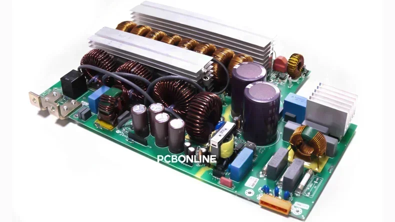
For high-power FR4 PCBs used for power supplies, inverters, motor drives, DC buses, etc, you can refer to the below to determine the PCB copper oz for outer layers. You must avoid hot spots, sharp angles, and bottlenecks.
Outer layer PCB copper oz for power supplies and stable designs, ΔT≈30°C
|
PCB copper oz
|
Current (A)
|
Trace width (mm)
|
|
1 oz
|
5
|
1.2
|
|
10
|
3.0
|
|
|
20
|
6.5
|
|
|
30
|
11.0
|
|
|
2 oz
|
10
|
1.8
|
|
20
|
4.0
|
|
|
30
|
6.5
|
|
|
50
|
12.0
|
|
|
3 oz
|
20
|
2.8
|
|
30
|
4.5
|
|
|
50
|
8.5
|
|
|
80
|
15.0
|
|
|
6 oz
|
30
|
2.5
|
|
50
|
4.5
|
|
|
80
|
8.0
|
|
|
120
|
14.0
|
Outer layer PCB copper oz for inverter boards, ΔT≈40°C
|
PCB copper oz
|
Current (A)
|
Trace width (mm)
|
|
1 oz
|
5
|
0.9
|
|
10
|
2.2
|
|
|
20
|
4.8
|
|
|
30
|
8.0
|
|
|
2 oz
|
10
|
1.4
|
|
20
|
3.0
|
|
|
30
|
5.0
|
|
|
50
|
9.0
|
|
|
3 oz
|
20
|
2.1
|
|
30
|
3.5
|
|
|
50
|
6.5
|
|
|
80
|
11.0
|
|
|
6 oz
|
30
|
1.8
|
|
50
|
3.5
|
|
|
80
|
6.0
|
|
|
120
|
10.5
|
|
|
8 oz
|
50
|
2.6
|
|
80
|
4.8
|
|
|
120
|
8.0
|
|
|
160
|
12.5
|
|
|
10oz
|
60
|
2.8
|
|
100
|
5.5
|
|
|
150
|
9.5
|
|
|
200
|
15.0
|
Local outer layer PCB copper oz for only DC-link, short path between MOSFET to capacitor, and busbar, ΔT≈60°C
|
PCB copper oz
|
Current (A)
|
Trace width (mm)
|
|
3 oz
|
30
|
2.5
|
|
50
|
4.8
|
|
|
80
|
8.5
|
|
|
120
|
14.0
|
|
|
6 oz
|
50
|
3.0
|
|
80
|
5.5
|
|
|
120
|
9.5
|
|
|
180
|
16.0
|
|
|
8oz
|
80
|
3.8
|
|
120
|
6.5
|
|
|
180
|
11.0
|
|
|
240
|
18.0
|
|
|
10 oz
|
100
|
4.0
|
|
150
|
7.5
|
|
|
220
|
13.0
|
|
|
300
|
21.0
|
|
|
12 oz
|
120
|
4.5
|
|
180
|
8.5
|
|
|
260
|
15.0
|
|
|
350
|
24.0
|
When the current is of 300A and above, high-frequency pulse + large di/dt, or the pad is significantly narrower than the busbar, adding PCB copper oz is far from meeting the PCB requirement. You should consider adding copper inlays/strips/busbars, or multilayer busbar stacking.
A 10-layer rigid-flex PCB with a 4-layer FPC core is used when signal density or EMI shielding is a priority, such as high-end smartphone camera modules or foldable devices where high-speed data (like MIPI CSI) must pass through the flex layers. The busbar equivalent cross-sectional area should be equal to or exceed the pin equivalent cross-sectional area × 1.2.
Partner with PCBONLINE for PCBs with Different Copper Thicknesses from 0.5oz to 14oz
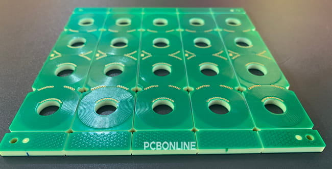
If you need one-stop FR4, rigid-flex, HDI, high-frequency, or heavy-copper PCB manufacturing and assembly, you can partner with PCBONLINE. PCBONLINE is an OEM PCB manufacturer that provides PCBs with copper thickness from 0.5oz to 14oz.

Founded in 2005, PCBONLINE has two large advanced PCB manufacturing bases, one PCB assembly factory, stable supply chains, and an R&D team for one-stop PCBA manufacturing.
PCBONLINE has strong PCB manufacturing capabilities, including FR4 PCB layers from 1 to 64, thick-copper PCBs up to 14oz, HDI PCBs, high-frequency PCBs, flexible PCBs, rigid-flex PCBs, aluminum PCBs, copper-based PCBs, and ceramic PCBs.
PCBONLINE grabs mature technologies for 10-layer PCBs, including controlled vacuum lamination for 10-layer rigid-flex and HDI structures, CO2 and UV laser drilling for 2+N+2 and 3+N+3 HDI configurations.
PCBONLINE offers free design for manufacturing (DFM) for your 10-layer PCB and PCBA project, including checking Gerber, bill of materials (BOM), testing files, and solving all technical and unexpected issues during prototyping to ensure the smooth and successful massive production.
PCBONLINE can do the R&D for your PCBA project or take part in your project's development from the early stage for the optimum PCB design and prevent tricky problems in the field application engineering (FAE) stage.
One-stop PCB services meeting your custom needs, including prototyping/sampling, PCB manufacturing, component sourcing, PCB assembly, PCBA value-added, testing, enclosure, and box-build assembly.
High-quality advanced PCB manufacturing certified with ISO 9001:2015, ISO 14001:2015, IATF 16949:2016, RoHS, REACH, UL, and IPC-A-600 Class 2/3.
No matter what applications your PCB will be used for, like GPU AI servers, automotive, aerospace, medical devices, industrial controls, and consumer wearables, PCBONLINE can produce and assemble PCBs that meet the highest performance and reliability standards. To get a quote for your PCB project, contact info@pcbonline.com.
Conclusion
Measuring copper in oz is a legacy industrial convention. Choosing the correct PCB copper oz depends on the temperature increase and current, and different PCB copper oz corresponds to different trace widths. If you're designing a PCB, PCBONLINE can provide one-stop PCB manufacturing for you with one-on-one engineering support.
PCB assembly at PCBONLINE.pdf
PCB fabrication at PCBONLINE.pdf


