
Inverter boards change the direct current (DC) into alternating current (AC). In automotive power, especially the electric vehicle power system's AC motor, the inverter board converts the DC power from the battery into AC power with adjustable frequency and voltage, which controls the motor's speed and torque. In industrial controls, the inverter board is the core of the variable frequency drive (VFD), which first rectifies the AC power into DC power, and then the inverter converts it back into frequency-adjustable AC power.
PCBONLINE provides turnkey inverter board assembly for industrial controls and automotive, from prototypes to batch PCBA production.

Components of Inverter Boards
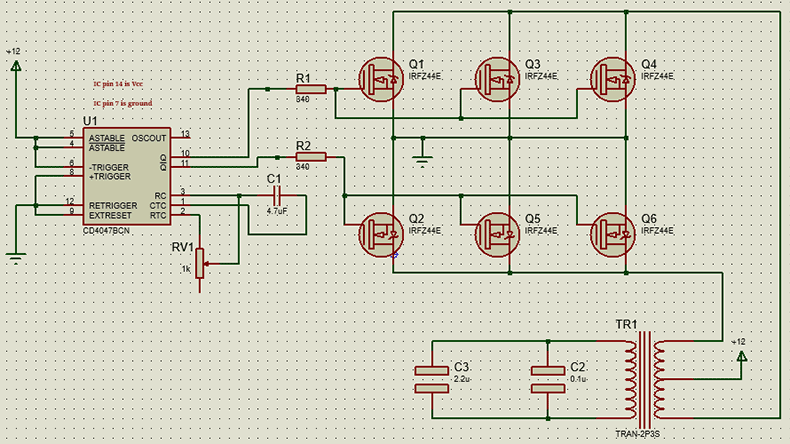
An inverter board is a high-power printed circuit board mounted with the power transistor/semiconductor switch (MOSFET, IGBT, SiC), MCU, driver IC, capacitors, inductors, busbars, voltage sensor, and temperature sensor (NTC). Heatsinks may also be mounted onto the inverter board for further thermal dissipation.
In the inverter board, the MCU runs complex algorithms, such as PWM pulse width modulation. It precisely calculates whether the transistor should be on or off every microsecond, thereby outputting a perfect sine wave. Usually, the signal emitted by the MCU is weak at only 3.3V, which cannot directly drive the MOSFET or IGBT switch, so there's also a driver IC mounted on the inverter board to amplify the signal.
The power transistor (MOSFET, IGBT, SiC) on the inverter board converts the DC into a fluctuating analog AC by rapidly switching on and off. In industrial control and automotive power applications, IGBTs (insulated gate bipolar transistors) or the more advanced SiC (silicon carbide) modules are increasingly being used.
Capacitors absorb fluctuations at the DC end, ensuring a stable voltage.
Inductors/transformers are used for voltage boosting (converting low-voltage DC to high-voltage AC) or smoothing the output current, reducing harmonic distortion.
For thermal management, power transistors are typically mounted against heavy aluminum or copper heat sinks. Thermal paste or thermal pads are also applied between the transistors and the heat sink. What's more, the traces on the inverter PCB are very thick of 4oz, 5oz, 10oz, usually several or even ten times thicker than standard PCB, to carry hundreds or thousands of amperes of current without burning out.
For security, there are also sensors on the inverter board. Current/voltage sensors provide real-time monitoring, and if the motor stalls or a short circuit occurs in the power grid, the MCU will shut down the output within microseconds to prevent the inverter board from failing catastrophically. Temperature sensors (NTCs) monitor the heatsink temperature, reducing power or activating cooling fans as needed.
Features of Inverter Board PCB Design
An inverter board is a thick-copper PCB with 3oz and above copper thicknesses for thermal management and power efficiency. The inverter board's PCB design features separating high and low currents using copper busbars and PCB traces to solve the conflict between efficiency and control accuracy. Its design also features solder mask opening & tinning, and creepage distance.

Thick copper
Standard PCB copper thickness is 1oz, while the copper thickness of inverter boards is 3oz to 14oz.
- High current handling: Inverters often output currents of tens or even hundreds of amperes. Thick copper significantly reduces line resistance and minimizes power loss.
- Enhanced heat dissipation: Copper is an excellent thermal conductor. The thick copper layer acts like a "built-in heatsink," quickly dissipating the heat generated by IGBTs or MOSFETs across the entire board or to the heatsink, preventing localized overheating and damage.
- Mechanical strength: High-power components (such as large inductors and capacitors) are heavy. The thick copper increases the structural strength of the board, preventing cracks from forming due to vibration (such as during vehicle operation).
Separation design of copper busbars and PCB traces
The strategy of PCB busbars for high currents and PCB traces for low currents is a core principle of power electronics design, including inverter boards for industrial controls and automotive.
Copper busbars are used for a high-current network. For paths with extremely high currents, such as battery input terminals and three-phase AC output terminals, thick copper PCBs are sometimes insufficient. In this case, designers use copper busbars, which are independent thick metal strips, directly soldered or bolted to the inverter PCB board.

The busbars' cross-sectional area far exceeds that of PCB traces, resulting in very low temperature rise and low inductance, effectively suppressing voltage spikes during inverter switching.
Thin PCB traces are used for a low-current network. MCU, sensor sampling signals, drive control signals, etc., belong to "low-voltage" circuits. These lines are thin and require extremely high resistance to electromagnetic interference (EMI).
In the PCB design, high-current paths are kept as far away as possible from sensitive sampling circuits. Even interlayer isolation is used. For instance, in multilayer PCB boards, control signals run on the inner layers, and high currents run on the outer layers.
Besides, the inverter board PCB design adopts solder mask opening & tinning for power integrity, and creepage distance for safety & isolation.
Many inverter boards have the solder mask stripped away (exposed copper) along high-current paths. During PCB fabrication, these exposed copper areas are either heavily built up with a thick layer of solder or manually reinforced with a thick copper wire to cost-effectively increase the cross-sectional conductive area.
Inverter boards involve high voltages. It is common to see slotting (routing out sections of the PCB) in the PCB design to prevent arcing or flashover between high-voltage and low-voltage sections, especially in humid or contaminated environments.
Inverter Board Assembly for Automotive and Industrial Control
Due to the heavy copper and the PCB busbars, the inverter board assembly requires significantly higher heat input than standard PCBs. While typical reflow profiles peak at around 245°C, inverter boards require higher peak temperatures (up to 260°C - 265°C) or significantly extended soaking times to ensure the high thermal mass components reach the wetting temperature.
Besides, inverter boards rely heavily on through-hole technology (THT) for large components like capacitors and heat sinks. This places strict requirements on solder vertical fill (hole fill) and solder volume. Achieving a 100% fillet on thick copper plates is difficult because the copper acts as a heat sink, causing the solder to solidify prematurely.
There is a conflict between soldering and cooling in the inverter board assembly. Consequently, the requirements for the thermal management system and the precision of the soldering profile are extremely high to prevent cold joints or insufficient wetting.
PCBONLINE has rich experience in high-power inverter board assembly for industrial control and automotive applications. We pay attention to wave soldering fixture design, reflow and wave soldering oven temperature control, and manufacturing process design. We can also offer selective soldering to replace wave soldering for preventing soldering defects and component displacement if needed.

Regarding the quality control of inverter boards for automotive and industrial control, we have four-terminal sensing during PCB fabrication to eliminate lead resistance for precise low-resistance measurement. We also have copper thickness inspection. During inverter board assembly, we have dual automated optical inspections (AOI) and X-ray inspection to ensure that the solder joints inside the thick-copper through-holes meet Class 3 standards.
All of the inverter boards we manufacture and assemble for automotive and industrial control are certified with IPC-A-610 Class acceptance standards.
Partner with PCBONLINE for Inverter Board Assembly
PCBONLINE is an OEM industrial control and automotive PCB assembly manufacturer providing free DFM (design for manufacturing) and one-stop PCBA manufacturing. You can work with PCBONLINE to turn your design into real inverter boards, from prototypes to mass production.
Founded in 2005, PCBONLINE has two large advanced PCB manufacturing bases, one PCB assembly factory, an R&D team, and stable supply chains for components and materials.
PCBONLINE has dominant advantages in industrial control and automotive inverter boards. We can deal with power management, jig design, temperature control, PCB optimization, and resistance control excellently.
We have comprehensive production lines and equipment for inverter board assembly, from PCB manufacturing and assembly, to tests and value-added, including four-terminal sensing, copper thickness inspection, etc.
PCBONLINE offers free DFM before and during PCBA prototyping to debug design defects and solve unexpected issues to ensure the success of your inverter board, including Gerber, BOM, manufacturing process design, testing, burn-in, IC programming, and enclosure.
We have advantages in high-power PCB manufacturing and assembly, including thick-copper PCBs 3oz to 14oz, copper busbars, and wave soldering for large THT components without displacement.
Our one-stop inverter board PCB assembly capabilities include independent advanced manufacturing, 4 automatic SMT lines, 4 THT assembly, 2 X-ray inspection machines, 1 first article inspection system, conformal coating machines, burn-in cabinets, IC programmers, a component warehouse, stable supply chains, an R&D team, etc.
When your inverter board assembly project goes to mass production, PCBONLINE will refund you the fees of R&D, prototyping/sampling, and offer free PCBA functional testing.
High-quality inverter board assembly and final product assembly certified with IPC-A-610 Class 3, ISO 9001:2015, IATF 16949:2016, RoHS, REACH, and UL.
PCBONLINE has manufactured many successful inverter boards for industrial control and automotive applications. To get a quote for your project's inverter board assembly, please email info@pcbonline.com. Once you contact us, we will provide you with one-on-one engineering support.
Conclusion
Inverter boards are high-power and thick-copper PCBs through-hole mounted with large capacitors, heatsinks, and inductors, and surface-mounted with an MCU and driver IC. Inverter boards assembly for industrial control and automotive requires copper thickness test, four-terminal sensing, and IPC-A-610 Class 3 acceptance standards. To ensure the success of your inverter board project for industrial control and automotive, get DFM and one-stop PCBA manufacturing services from the industrial control and automotive PCB assembly manufacturer PCBONLINE.


