
Electronic design is no longer flat. As consumer electronics shrink and medical devices become wearable, engineers face a major challenge. They must fit complex circuitry into tight, irregular, and often moving spaces.
The days of relying solely on standard, rigid fiberglass (FR-4) PCBs are over. Today, hardware teams choose between flexible PCBs, rigid-flex PCBs, and PCB-on-PCB architectural approaches.
The stakes for this decision are high. The global flexible PCB market was valued at USD 23.89 billion in 2024. Driven by booming demand in consumer electronics and telecom, it is projected to reach USD 50.90 billion by 2030, growing at a remarkable 13.7% CAGR.
If you are designing a compact device, this guide will help you choose the right approach. We will break down the materials, industry standards, design constraints, and manufacturing steps you need to know.
Flexible PCB, Rigid-Flex PCB, & PCB-on-PCB
Understanding the core differences in materials and structures is the first step in making an informed design choice.
Flexible PCBs (FPCs)
A flexible PCB is a printed circuit board built to bend, fold, or flex. Instead of rigid fiberglass, it uses a flexible polymer substrate. Polyimide (PI) is the industry favorite, accounting for 43.73% of the flexible substrate market in 2025. PI offers excellent thermal stability and mechanical strength. For lower-cost or transparent applications, manufacturers also use PET (polyester) films.
Unlike a rigid PCB that uses a green epoxy solder mask, flex circuits protect their outer copper traces with a thin flexible film called a coverlay. This is made of polyimide or PET combined with an adhesive layer.
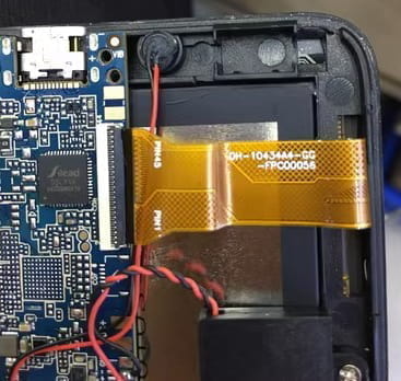
Rigid-flex PCBs
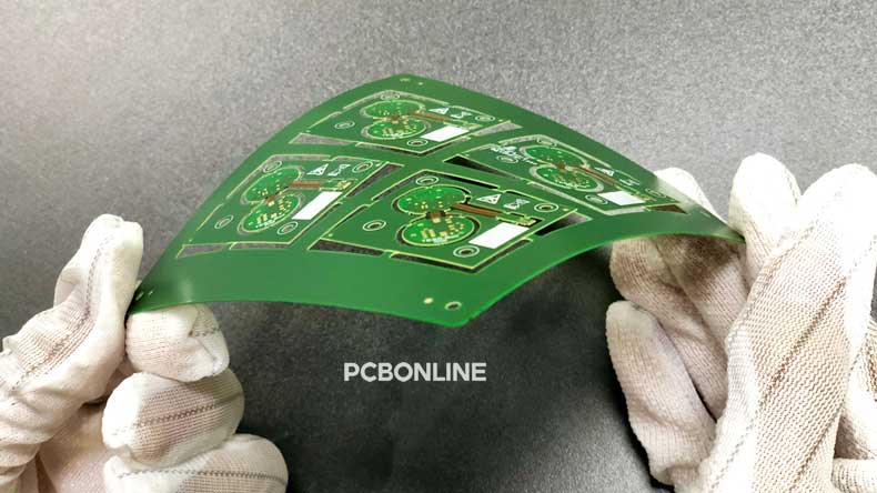
Rigid-flex PCBs combine the best of both worlds. They integrate FR4 outer layers and flexible PI layers into a single, seamless circuit board. The flexible layers run continuously through the entire assembly, including the rigid zones. This eliminates the need for bulky connectors and ribbon cables, saving space and reducing weight.
PCB on PCB
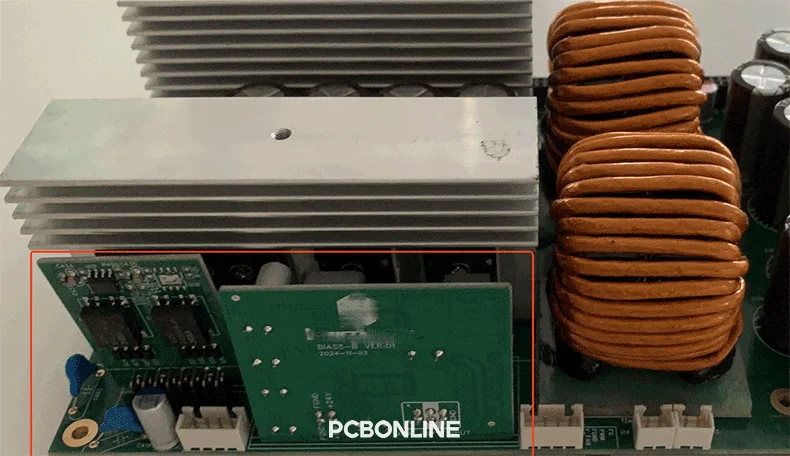
PCB on PCB often refers to modular assemblies where smaller rigid or flexible PCBs are mounted directly onto a larger main PCB. When used to create multi-axis, folded designs, a PCB-on-PCB setup can closely resemble a rigid-flex structure. However, it relies on surface-mount soldering or specialized headers to make the physical and electrical connections between the boards.
The IPC-6013 Standard
Before releasing a design to production, you must understand how international quality standards classify these PCBs. IPC-6013D is the foundational document for flexible printed boards. It defines five specific types of constructions:
- Type 1: Single-sided flexible printed boards containing one conductive layer.
- Type 2: Double-sided flexible printed boards containing two conductive layers with plated through-holes. This is the most common style, accounting for 46.1% of global flex revenue in 2024.
- Type 3: Multilayer flexible printed boards containing three or more conductive layers with plated through-holes.
- Type 4: Multilayer rigid-flex combinations containing three or more conductive layers with plated through-holes.
- Type 5: Flexible or rigid-flex printed boards containing two or more conductive layers without plated through-holes.
Installation Use Cases: Use A vs. Use B
IPC-6013 also categorizes how the PCB will handle stress during its operational life. You must specify this in your engineering drawings:
- Use A (Flex-to-install): the PCB only needs to bend during assembly or maintenance. Once nestled inside the enclosure, it remains completely stationary.
- Use B (Continuous flex): the PCB will bend dynamically throughout its life. Think of a laptop hinge opening and closing, or a moving print head in an inkjet printer.
- Use C: High-temperature environments exceeding 105°C.
- Use D: Applications requiring specific Underwriters Laboratories recognition.
Design Rules for Flex and Rigid-Flex
Designing a flexible circuit requires a deep understanding of mechanical physics. If you don't design for stress, the copper traces will crack.
Bend Radius and Location
You cannot treat the bend radius as an afterthought. It must be defined before you route a single trace. The bend radius is the minimum radius the circuit can safely bend without damaging the materials.
IPC guidelines recommend strict minimum bend radius multiples based on your layer count and total circuit thickness:
|
Flex type
|
Minimum bend radius
|
|
Single-sided
|
6 × circuit thickness
|
|
Double-sided
|
10 × circuit thickness
|
|
Multilayer
|
20 × circuit thickness
|
To maximize your bend performance, keep the flexing area as thin as practically possible.
Component Placement and Stiffeners
Components should never be placed directly inside a bend zone. The stress of the bend will crack the solder joints or pull the pads clean off the PCB. If you must place components on a flexible circuit, you need to use a stiffener.
Stiffeners are rigid pieces of material added to the back of a flex zone to provide mechanical support. Common options include:
- Polyimide (PI) stiffeners: Used to thicken specific areas, like behind gold finger contacts that plug into a Zero Insertion Force connector.
- FR4 stiffeners: Thick fiberglass pieces that provide a flat, rigid base for mounting surface-mount (SMD) components.
- Stainless steel stiffeners: Used when maximum rigidity is required in an ultra-thin profile.
Comparing Structural and Material Limitations
When choosing between standard Flex and Rigid-Flex, you must balance your performance goals against the technical capabilities of your fabrication partner.
Every manufacturer has distinct limits. For instance, advanced turnkey PCB fabricators like PCBONLINE offer a clear look at what is possible with precision manufacturing:
- Layer limits: Pure polyimide flex circuits can typically be built up to 10 layers, while transparent PET flex tops out around 6 layers. For rigid-flex boards, capabilities vary wildly based on equipment. PCBONLINE lists overlapping maximums of 24 and 64 layers across different service categories, meaning you should always verify exact stackups with their engineering team before quoting.
- Thickness options: Finished rigid-flex assemblies can range anywhere from 0.2 mm to 4.0 mm thick.
- Spacing constraints: The minimum physical width for a dedicated flex layer is typically 2.5 mm. When transitioning between rigid and flexible zones on a rigid-flex board, a spacing of 3 mm is preferred, though specialized processes can push down to a 2 mm limit.
- Trace and space precision: High-density designs require incredibly tight tolerances. Advanced lines can support a minimum line width and spacing of just 0.035 mm / 0.035 mm, with an interlayer alignment tolerance of ±0.05 mm.
FPC Assembly Challenge
Assembling components onto a flexible circuit is different from handling a rigid PCB. Because the material is thin and pliable, it will sag and warp under the weight of solder paste and components.
The assembly workflow
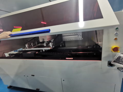
To build an FPC assembly successfully, advanced manufacturers like PCBONLINE use a specialized Surface Mount Technology (SMT) assembly line to finish the process below:
[Custom jig fixing] ➔ [Solder paste printing] ➔ [Solder paste inspection] ➔ [Component placement] ➔ [Reflow soldering] ➔ [Automated optical inspection (AOI)]
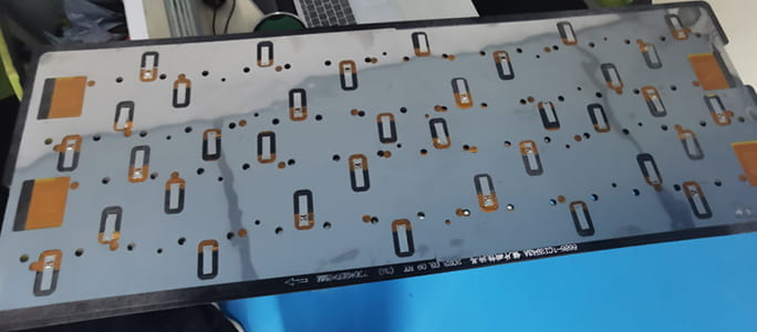
First, operators place the flexible PCB into a custom-machined rigid jig. This jig holds the film perfectly flat. Next, the assembly passes through an SMT line specialized for flexible PCBs: paste printing, high-speed component placement (supporting tiny footprints down to 01005), and reflow soldering. Finally, AOI verifies the placement before the PCB is removed from its carrier.
Rigorous post-assembly testing
Flexible circuits face harsh environmental and mechanical conditions. A comprehensive quality control process must include a battery of tests to guarantee long-term reliability:
- Mechanical integrity: Tension testing, continuous bending lifecycle tests, and button-strike life testing.
- Environmental resistance: High-temperature environmental simulation, hand sweat exposure, and salt spray testing for corrosion.
- Electrical performance: DC resistance tracking, precise high-frequency voltage checks, and single-ended impedance validation. Typically, single-ended impedance tolerances are held to ±3 Ω for lines up to 50 Ω, and ±8% for lines above 50 Ω.
Applications across Modern Industries
Flexible and rigid-flex technologies have completely revolutionized product architecture across multiple sectors.
- Consumer electronics: This sector represents 38.62% of the flexible PCB market revenue. Flex circuits are what make thin smartphones, compact camera modules, and vibrant wearable displays possible.
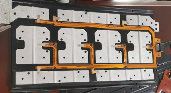
- Automotive technology: Flex electronics power modern automotive lighting assemblies and complex instrument panels. They are also vital for electric vehicles, forming the ultra-reliable cell contact systems used to monitor lithium-ion battery packs.
- Medical electronics: FPCBs are used in flexible medical "skins," hearing aids, and biocompatible research implants where rigid electronics would be too bulky or dangerous.
- Aerospace and Telecom: High-density data transmission systems rely on the weight savings and vibration resistance of integrated rigid-flex assemblies. The telecom segment alone is expected to maintain a steady 7.11% CAGR through 2031.
The Ultimate Buyer's Checklist
When compiling your request for quote for a flex or rigid-flex project, use this checklist to ensure you receive accurate pricing and avoid manufacturing delays.
Because custom flex designs feature unique stackups and raw material costs, fabricators do not offer public pricing tables, cycle-life specifications, or standard lead-time sheets. Every quote is fully tailored to your design files.
- Specify the IPC type: Clearly state if your design is Type 1 (single-sided flex) through Type 4/5 (multilayer rigid-flex).
- Define the use case: Explicitly state whether the PCB is Use A (flex-to-install) or Use B (continuous dynamic flex).
- Document the bend parameters: Include your intended bend locations and minimum bend radius calculations directly in your fabrication notes.
- Detail the stiffener requirements: Provide precise drawings showing the locations, thicknesses, and materials (FR-4, PI, or Stainless Steel) for all stiffeners.
- Identify surface finishes: Choose a finish suited to your application—such as Electroless Nickel Immersion Gold (ENIG), Organic Solderability Preservatives (OSP), Electroless Nickel Electroless Palladium Immersion Gold (ENEPIG), or Immersion Tin.
- Verify specialized via specs: If your rigid-flex design utilizes high-density interconnect (HDI) features, verify that your fabricator can support your required microvia sizes (e.g., minimum laser blind hole apertures of 0.1 mm).
- Confirm fabricator capabilities: If your design pushes the envelope with layer counts (such as a 24+ layer rigid-flex board), large panel sizes, or ultra-thin 0.035 mm trace widths, contact your fabricator directly to confirm their live testing and production limits.
PCBONLINE: The Turnkey Partner for Flexible, Rigid-flex, and Rigid PCBs
For terminal companies that require flexible, rigid-flex, and rigid PCBs with the flexibility of a turnkey partner, PCBONLINE is the strategic solution.
We provide flexible circuit one-stop solutions, including R&D, manufacturing, and assembly. Founded in 2005, PCBONLINE has an FCCL factory, two FPC manufacturing bases, and a turnkey flex PCB assembly factory, with stable supply chains and an R&D team.
PCBONLINE has turnkey flex PCB fabrication and assembly capabilities. We not only fabricate and assemble FPCs, but also provide flex PCB copper-clad laminates custom for FPC fabrication.
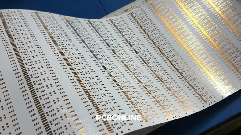
Powerful FPC manufacturing capabilities, including transparent PET FPC, 1 to 8-layer PI FPCs with a maximum length of 200m, HDI, and rigid-flex FPCs.
PCBONLINE does comprehensive tests, such as ensuring the bend radius, the tension test, bending test, button strike life test, hand sweat test, environmental protection test, metallographic microscope inspection, bridge test, etc.
PCBONLINE has flex PCB R&D capabilities and can do the FPC design or take part in your project's development from the early stage.
PCBONLINE provides free DFM (design for manufacturing) and one-on-one engineering support for FPC projects, including FPC layout optimization.
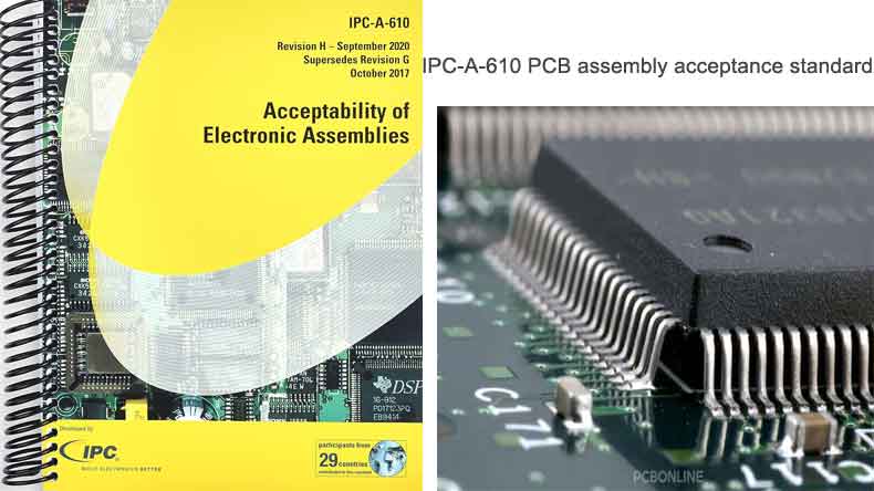
High-quality flex PCB assembly certified with ISO 9001:2015, ISO 14001:2015, IATF 16949:2016, RoHS, REACH, UL, and IPC-A-610 Class 2/3.
The professional team at PCBONLINE specializes in thermal management, signal integrity, fixture design, and manufacturing process control. We ensure the flex PCB assembly is tailored to your project's custom requirements. To get a quote for your flexible circuit project, please contact info@pcbonline.com.
Flex PCB fabrication video of PCBONLINE
Conclusion
Choosing between a pure flexible PCB, a complex rigid-flex board, or a modular PCB-on-PCB assembly comes down to a balance of space, structural requirements, and budget. While standard flex offers incredible weight and space savings for simple bends, rigid-flex provides an elegant, connector-free solution for highly intricate 3D designs. PCBONLINE offers the advanced FPC, rigid-flex, and rigid PCB manufacturing capabilities of a global leader with the service-oriented approach of a turnkey partner. From our own laminate production to specialized FPC assembly, we are the one-stop shop for your most flexible ideas.


