
Semi-flex PCBs are also called rigid-flex PCBs, and their design structure is as symmetrical as possible. We manufacture semi-flex PCBs from 2 to 16 layers, and the inner flexible PCB layers we can make are 1, 2, 4, and 6. The flex core can't go beyond 6 layers; otherwise, it loses its flexibility. Our semi-flex PCBs are not connected by the so-called rigid sections and flexible sections, but the flex core laminated with the outer FR4 PCB layers, and then we use laser to precisely remove the unwanted FR4 areas to expose the flexible PI PCB areas for bending.
Semi-Flex PCB Design Principle: Symmetry
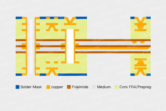
With a semi-flex PCB, you don’t need to use connectors or cables to join separate PCBs, as it is an integrated unit. It consists of a PI (polyimide) flexible printed circuit (FPC) core that is laminated with FR4 outer circuit layers.
A critical design principle of semi-flex PCB is symmetry. A symmetrical stackup ensures the reliability and manufacturability of the PCB.
A 2-layer rigid-flex PCB composed of a rigid and a flex PCB layer, so it is symmetrical and complex to manufacture. However, PCBONLINE can manufacture 2-layer semi-flex PCB to achieve material balancing by internal stress balancing, controlled lamination, and depth-controlled laser.
2-layer semi-flex PCB is the only rigid-flex PCB that can be made with an asymmetrical structure because its small layer quantity allows PCB manufacturers like PCBONLINE to achieve balancing in manufacturing.
How about a 3-layer semi-flex PCB with the flex PCB layer sandwiched between two rigid layers? 3-layer semi-flex PCBs are very rare, though they look perfectly balanced on a 2D diagram.
Symmetry in semi-flex PCB manufacturing isn't just about the position of layers but also about the balancing of materials.
A 3-layer semi-flex PCB consists of a 2-layer core plus 1 layer of copper foil added via a prepreg layer. Because the flexible PI and the rigid FR4 have different Coefficients of Thermal Expansion (CTE), they expand and contract at different rates when heated.
Even if the flex layer is in the middle, the top half of the PCB is a rigid core while the bottom half is just a single layer of copper and prepreg. This causes the PCB to warp during the cooling process after lamination.
For the symmetrical position of layers and balancing of materials, semi-flex PCBs are the only 2-layer semi-flex PCB that can achieve balance in manufacturing and the 4-, 6-, 8-, ..., 16-layer semi-flex PCBs in a symmetrical structure.
Symmetry of the layer position and balancing material during PCB fabrication are necessary for semi-flex PCBs, with the advantages of:
Preventing warpage: Symmetrical designs balance the mechanical stress between the FR4 and PI layers. If the stackup is unbalanced, the PCB is highly prone to warping or twisting during the high-temperature lamination and soldering processes.
Uniform expansion: Because FR4 and Polyimide have different CTE, a symmetrical layout ensures that thermal expansion occurs evenly, protecting the integrity of the plated through-holes and internal traces.
Technical Capabilities and Layer Limits of Semi-Flex PCBs
To maintain the structural integrity and the bendability of the circuit, there are some engineering constraints regarding layer counts.
Total layer count: Semi-flex PCBs can be manufactured from 2 to 16 layers in total.
Flexible core limits: The internal flex core can consist of 1, 2, 4, or 6 layers. Beyond the 6-layer limit, the core loses the flexibility required for its application, which could lead to mechanical fatigue.
Here's the technical capabilities at PCBONLINE:
|
Feature
|
Capability at PCBONLINE
|
|
Flexible circuit layer
|
1 to 6
|
|
Rigi-flex PCB layer
|
2 to 16
|
|
Flex layers on the outer or middle
|
Middle
|
|
Finished PCB thickness
|
0.2mm to 4.0mm
|
|
Tolerance of PCB thickness
|
>1.0mm, ±10%
≤1.0mm, ±0.1mm |
|
Adhesive flex PCB
|
SF305: PI=0.5mil, 1mil, 2mil; Cu=0.33oz, 0.5OZ, 1OZ
R-F777: PI=1mil, 2mil, 3mil, 4mil; Cu=0.5oz, 1oz |
|
Low-flow prepreg (PP)
|
VT-47N, VT-901LF, EM-37B
|
|
standard FR4
|
IT-180A, S1141, S1000-2, TU-768 (TU-752)
|
|
High-performance FR4
|
Arlon 85N, Rogers RO4350B series, Ventec VT-901, M6 series, R-5775, TUC TU-872SLK, TU-862HF
|
|
Impedance tolerance
|
Single-ended: ±3Ω (≤50Ω), ±8% (>50Ω)
Differential pair: ±4Ω (≤50Ω), ±8% (>50Ω) |
|
HDI type
|
3+n+3 (n buried hole≤0.4mm)
|
|
Min. twist & warp
|
0.75% (symmetrical)
1.5% (asymmetrical)l |
|
Min. distance between R-F connect area to conductors
|
0.3mm (half depth slot process)
0.5mm normal |
|
Min. distance between E-test pads
|
4mil
|
|
Max. flex circuit thickness
|
3oz
|
|
Min. distance between flex layer conductor and outline
|
10mil
|
One-Roof Manufacturing Advantages of Semi-Flex PCB
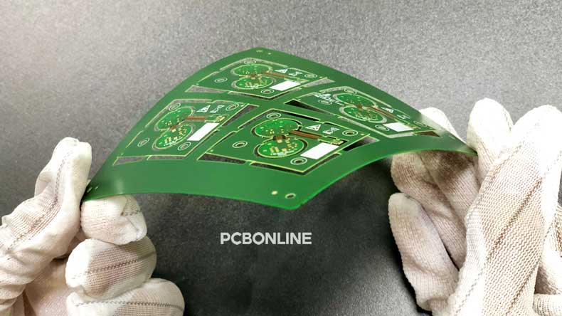
The semi-flex PCBs in the picture are manufactured by PCBONLINE. We offer rigid-flex PCB under one roof.

One of the primary challenges in rigid-flex production is the disparate nature of the materials. At PCBONLINE, we maintain both dedicated rigid FR4 and flexible PCB production lines within the same facility.
By handling the entire semi-flex PCB manufacturing process under one roof, we ensure:
- Material compatibility: Seamless integration of PI and FR4 substrates.
- Quality control: Tight oversight of the complex lamination and registration processes.
- Faster lead times: No delays caused by shipping sub-assemblies between different specialized factories.
Detailed Material Composition of The Flex Core
The heart of a semi-flex PCB is the internal FPC core. To ensure long-term reliability and flexibility, the core layers of our semi-flex PCBs use AD copper, Pl, and adhesive for the best flexibility.
- AD copper (annealed copper): We use AD copper rather than standard ED (electro-deposited) copper for the flex core of a semi-flex PCB. AD copper has a grain structure that allows it to withstand repeated bending without cracking.
- Polyimide (PI): PI serves as the core insulation and the coverlay. It is chosen for its exceptional thermal stability and mechanical flexibility.
- Adhesive: High-bond strength adhesives are used to laminate the AD copper to the PI core and to secure the protective coverlay.
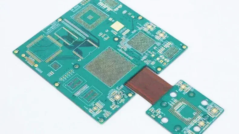
The Manufacturing Process of Semi-Flex PCB
The core step of semi-flex PCB manufacturing is the depth-controlled laser ablation.
Our semi-flex PCBs are not simply connected by separate rigid and flexible sections. Instead, we use a lamination-and-removal technique. The critical manufacturing steps in the rigid-flex PCB manufacturing are:
- Full lamination: The flexible polyimide core is laminated between the outer FR4 layers to create a solid stack.
- Laser precision: We use high-precision laser technology to precisely remove the unwanted FR4 areas.
- Exposure: This process exposes the internal flexible PI PCB areas for bending, while the remaining FR4 sections provide the structural rigidity needed for SMT assembly.
Applications of Semi-Flex PCBs
Semi-flex technology is applied in high-performance sectors. Semi-flex PCBs’ ability to fold into tight spaces makes them find applications in medical, aerospace, automotive, consumer wearables, and industrial robots.
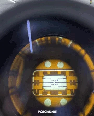
1. Medical & healthcare
As seen in our product photos, these boards are critical for Wearable Medical Devices and Elderly Swallowing Detection systems. The flexible sections allow the device to contour to the human body, while the rigid sections house sensitive BGA and QFN components.
2. Aerospace and avionics
Weight reduction is paramount in flight. Semi-flex PCBs eliminate bulky wire harnesses and connectors, reducing the overall weight of flight control systems and cockpit instrumentation.
3. Automotive electronics
Modern vehicles use semi-flex boards for LED lighting systems, infotainment displays, and engine sensors. Their ability to withstand the constant vibration of a vehicle while fitting into curved interior panels is a major advantage.
4. Consumer electronics & IoT
From foldable smartphones and tablets to compact IoT home security cameras, semi-flex PCBs allow designers to utilize 3D space within a device housing, rather than being limited to a flat plane.
5. Industrial robotics
In robotic arms and automated machinery, semi-flex boards provide the necessary flexibility for constant movement (dynamic flex) while maintaining the durability of FR4 for control circuitry.
Why choose semi-flex PCBs over rigid PCBs? Semi-flex PCBs provide the advantages of:
- Space savings: Ideal for ultra-compact designs where every millimeter counts.
- Increased reliability: Eliminating connectors between boards reduces the number of potential points of failure.
- Signal integrity: Controlled impedance and RF-friendly designs are easier to maintain in a continuous circuit than through mechanical headers.
Partner with PCBONLINE for Rigid-flex PCB Manufacturing Under One Roof
If you're looking for rigid-flex PCB manufacturing and assembly under one roof, work with the turnkey rigid-flex PCB manufacturer PCBONLINE. Our rigid-flex PCB capabilities and certifications match the requirements for automotive, medical, aerospace, computers, commercial, and communication industries.
Founded in 2005, PCBONLINE has two large advanced PCB manufacturing bases, one turnkey PCB assembly factory, stable supply chains, and an R&D team.
PCBONLINE has turnkey rigid-flex PCB fabrication and assembly capabilities for automotive and medical from PCB prototypes to mass assembly production.
Rigid-flex PCB fabrication requires both flex and rigid PCB fabrication lines and laser-cut equipment. PCBONLINE has complete equipment specialized for rigid-flex PCB fabrication.
The professionals from PCBONLINE can optimize rigid-flex PCB design to be the most economical without quality sacrifice for automotive and medical uses.
PCBONLINE provides free DFM (design for manufacturing) and one-on-one engineering support for rigid-flex PCB projects.
PCBONLINE does comprehensive tests ensuring the bend radius, long-term reliability, and micro resistance, including four-terminal sensing, the tension test, bending test, button strike life test, hand sweat test, environmental protection test, metallographic microscope inspection, bridge test, etc.
High-quality rigid-flex PCB certified with ISO 9001:2015, ISO 14001:2015, IATF 16949:2016, RoHS, REACH, UL, and IPC-A-610 Class 3.
The professional team at PCBONLINE specializes in creating high-quality semi-flex PCBs, tailored to your project's custom requirements. To get a quote for your rigid-flex PCB project, please contact info@pcbonline.com.
Conclusion
A semi-flex PCB is a flexible PCB laminated with FR4 layers. Symmetry and balancing are critical for semi-flex PCB design and manufacturing. To manufacture and assemble affordable semi-flex PCBs under one roof, work with the one-stop rigid-flex PCB manufacturer PCBONLINE.
PCB assembly at PCBONLINE.pdf
PCB fabrication at PCBONLINE.pdf


