
In today's electronics world, space is shrinking, while complexity and functionality are growing. Devices like foldable phones, wearable trackers, and smart medical instruments demand circuit boards that are flexible in form but rigid in performance.
Enter the rigid-flex PCB—a hybrid PCB that integrates both rigid and flexible layers into a single unified structure. This allows engineers to design compact, durable, and highly reliable circuits that can bend, fold, or twist without breaking.
In this article, we'll explore the technical foundation of rigid-flex PCBs, their real-world applications, design tips, common pitfalls, and walk through the design of a basic rigid-flex board.
In this article:
Part 1. What is a Rigid-flex PCB? Part 2. Rigid-flex PCB Stackup Part 3. Applications of Rigid-flex PCB Part 4. Rigid-flex PCB Design Choose a PCB House that Supports Rigid-flex StackupsWhat is a Rigid-Flex PCB?
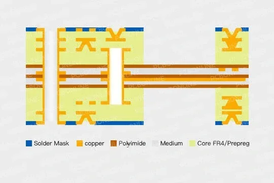
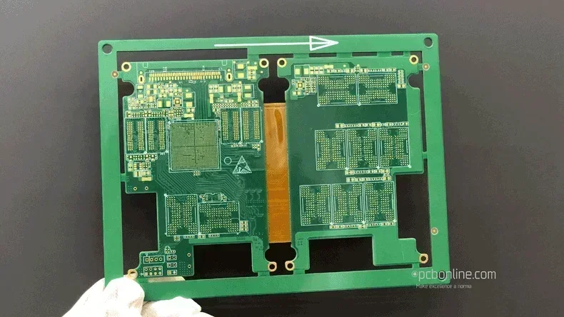
A rigid-flex PCB is essentially a flexible PCB laminated with FR4 PCB outer layers. After lamination, the unwanted areas in the FR4 PCB layers are laser cut to go off and expose the polyimide flexible inner layers.
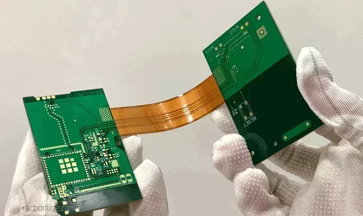
It combines traditional FR4-based rigid circuits with polyimide-based flexible circuits in a layered configuration. Unlike using separate flex cables and connectors to bridge rigid boards, a rigid-flex PCB is fabricated as a single unit, with copper traces extending seamlessly across both rigid and flexible layers.
Benefits of rigid-flex PCBs:
- Reduced size and weight: No connectors or ribbon cables needed.
- Higher reliability: Fewer solder joints = fewer failure points.
- Improved signal integrity: Continuous traces eliminate impedance mismatches.
- 3D design capability: Flex parts can fold and wrap around enclosures.
- Shock and vibration resistant: Better mechanical robustness in harsh environments.
Microvias penetrate only one rigid layer, so they are laser drilled and electroplated on the rigid layer before the lamination process. The positioning has to be highly precise. Therefore, HDI rigid-flex PCB manufacturing has a high scrap rate, and the board prices are higher than flexible PCBs and normal PCBs.
Rigid-flex PCB Stack-up
A rigid-flex PCB includes:
- PCB layers: 2-24 layers
- Flexible layers: 1-6 layers of polyimide with copper traces
- Adhesive: Epoxy or acrylic to bond rigid layers to the flex PCB core
- Coverlay: A protective layer is used in rigid-flex PCB core (flex PCB)
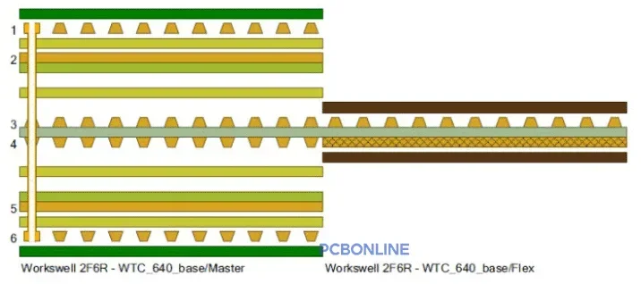
A typical stack-up of a 6-layer rigid-flex PCB is 2F6R as below.
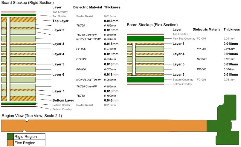
A typical stack-up of an 8-layer rigid-flex PCB is 4F8R. You can view its layers, dielectric materials, and their thicknesses:
|
PCB rigid-flex
|
Layer
|
Dielectric material
|
Thickness
|
|
Rigid layers
|
Top overlay
|
|
|
|
Top solder
|
Solder mask
|
0.018mm
|
|
|
Top layer
|
|
0.046mm
|
|
|
|
TU768
|
0.102mm
|
|
|
Layer 2
|
|
0.018mm
|
|
|
|
TU768 core + PP
|
0.406mm
|
|
|
|
NON FLOW TU84P
|
0.064mm
|
|
|
Flex layers
|
Top overlay
|
|
|
|
flex top coverlay
|
FC-001
|
0.051mm
|
|
|
Layer 3
|
|
0.018mm
|
|
|
|
PP-006
|
0.076mm
|
|
|
Layer 4
|
|
0.018mm
|
|
|
|
BT25X2
|
0.051mm
|
|
|
Layer 5
|
|
0.018mm
|
|
|
|
PP-006
|
0.076mm
|
|
|
Layer 6
|
|
0.018mm
|
|
|
Bottom coverlay
|
FC-001
|
0.051mm
|
|
|
Bottom overlay
|
|
|
|
|
Rigid layers
|
|
Non FLOW TU84P
|
0.064mm
|
|
|
TU768 Core + PP
|
0.406mm
|
|
|
Layer 7
|
|
0.018mm
|
|
|
|
TU768
|
0.102mm
|
|
|
Bottom layer
|
|
0.046mm
|
|
|
Bottom solder
|
solder mask
|
0.018mm
|
|
|
Bottom overlay
|
|
|
Applications of Rigid-flex PCB
Rigid-flex PCBs combine the best of both rigid and flexible circuit technologies, enabling high-performance, space-saving, and mechanically robust electronic designs. Their growing popularity across consumer electronics, medical, aerospace, and automotive industries is driven by their ability to reduce interconnects, enhance reliability, and fit into compact or dynamic enclosures.
The applications of rigid-flex PCBs are below.
Consumer electronics
- Smartphones and tablets: Internal interconnections between display, camera modules, and main boards.
- Wearables (smartwatches, fitness bands): Compact design and flexibility for curved shapes.
- Foldable devices: Flex section allows hinge-based bending without damage.
Medical devices
- Hearing aids: Ultra-compact and lightweight design.
- Diagnostic devices: Blood glucose monitors, ECG patches where flexible routing is needed.
- Endoscopy equipment: Flexibility for insertion into tight body cavities.
Automotive industry
- Instrument clusters and; HUDs: Combines multiple PCBs into compact modules.
- Airbag systems and sensors: Reliable, vibration-resistant connections.
- Infotainment systems: Integration of screens, buttons, and logic boards.
Aerospace and defense
- Avionics modules: Lightweight and vibration-resistant for flight environments.
- Missile guidance systems: Miniaturization with robust interconnections.
- Military wearables: Smart vests, headgear with embedded electronics.
Industrial automation
- Robotics: Movable joints and sensor integration benefit from flex PCBs.
- Control panels: High-density routing in compact machinery.
- Sensors in tight spaces: Ability to fold PCBs into mechanical assemblies.
Telecommunications
- Antennas and signal routing modules: Enable compact routing in network equipment.
- Base stations: Combines multiple functional zones with reduced interconnect failures.
Rigid-flex PCB Design
When designing a rigid-flex PCB, it's easy to fall into traps that can lead to performance issues or fabrication failures. Designing rigid-flex circuits requires careful planning to avoid common pitfalls like incorrect bend radii, inadequate stack-ups, or improper material choices.
Here's what to watch out for:
❌ Sharp bends in flex areas
Avoid 90° or tight bends. These can cause copper to crack. Use gradual bends with a minimum bend radius of 10x the flex thickness.
✅ Tip: Use curved traces and soft corners.
❌ 2. Vias in flexible regions
Placing vias in the flex part can lead to stress fractures during bending. Avoid them unless specialized stacked or staggered vias are supported by your manufacturer.
✅ Tip: Keep all vias in rigid zones.
❌ 3. No stiffener under flex components
If you mount components on a flexible area without a stiffener (reinforcement layer), the area can flex during operation or soldering, damaging solder joints.
✅ Tip: Apply stiffeners under components in the flex region.
❌ 4. Ignoring material compatibility
Standard FR4 and polyimide expand and contract differently. Improper selection of adhesive or copper weight can lead to delamination or warping.
✅ Tip: Follow your fab house's rigid-flex material guidelines.
❌ 5. Routing traces along the bending axis
Traces should be routed perpendicular to the bending axis to reduce mechanical stress on copper.
✅ Tip: Use teardrop pads and curved routing in flex areas.
❌ 6. Incorrect layer stack-up in CAD
✅ Tip: Use the Layer Stack Manager in the PCB design tool to define rigid and flex layers clearly.
Step 1: Create a new project
- Open the PCB design tool on your computer.
- Click + New Project.
- Name your project
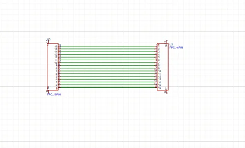
Step 2: Draw the schematic
Add components.
Step 3: Convert to PCB and set the board Outline
- Click Convert to PCB.
- Draw the PCB outline with three zones: rigid-flex-rigid.
Step 4: Define rigid and flex regions
- Go to Layer Stack Manager.
- Set the middle section as "flex" and assign appropriate layers.
- Keep the outer layers of the outer zones as rigid.
- Add mechanical drawings if needed to communicate bend zones.
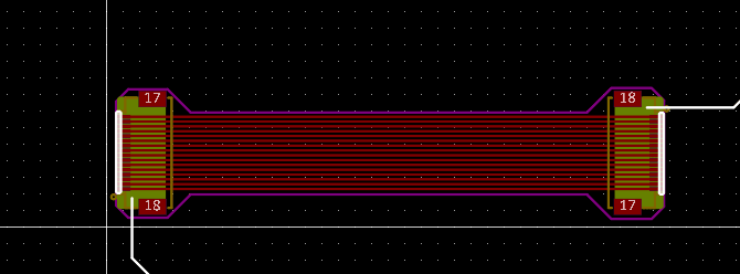
Step 5: Route traces carefully
- Keep traces away from flex/rigid transitions.
- Use rounded corners and wide trace-to-trace spacing in flex.
- Avoid vias in the flex section.
- Place critical components on rigid zones.
Step 6: 3D preview and export Gerbers
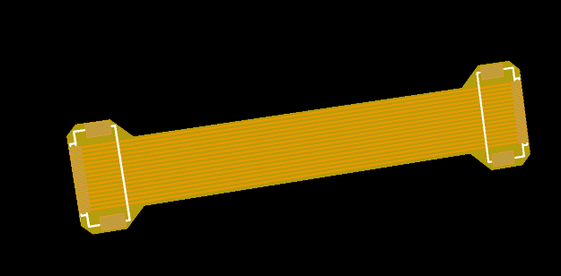
- Use the 3D viewer to check alignment and enclosure fit.
- Once satisfied, export Gerber files for fabrication.
Choose a PCB House that Supports Rigid-flex Stackups
If you are looking for turnkey electronic manufacturing for your rigid-flex project, you can PCBONLINE is a leading rigid-flex PCB manufacturer in China that serves clients around the world. You can order rigid flex PCB manufacturing, assembly, and components altogether from PCBONLINE from prototyping to large-scale manufacturing. PCBONLINE is a recommended rigid flex PCB manufacturer for these reasons:

PCBONLINE has powerful rigid-flex PCB capabilities, such as 2-24 layers, HDI 4+N+4, FR4/PI/steel stiffeners.
PCBONLINE offers a free DFM review before production to ensure the manufacturability of the rigid-flex PCB stackup and solve any technical issues.
Our experienced R&D and engineering team provides one-on-one engineering support throughout the project, including rigid-flex PCB stackup optimization.
Turnkey OEM rigid-flex PCB services, including prototyping, PCB fabrication, components, rigid-flex PCB assembly, tests, enclosures, box-build assembly, and value-added services.
High-quality rigid-flex PCB manufacturing certified with ISO 9001:2015, ISO 14001:2015, IATF 16949:2016, RoHS, REACH, UL, and IPC-A-600 Class 2/3.
When your rigid-flex project enters the bulky production stage, PCBONLINE refunds the fees of R&D, prototyping, and PCBA functional testing.
Please take a look at PCBONLINE's capabilities in rigid-flex PCB manufacturing:
|
Features
|
PCBONLINE's Rigid Flex PCB Capabilities
|
|
Layers
|
PCB layers: 2 to 24, flex layers: 1 to 6
|
|
Build time
|
1 day to 4 weeks
|
|
Board size
|
Min. 4mm×4mm to Max. 457mm×610mm
|
|
Final board thickness
|
0.05mm to 0.6mm
|
|
Materials
|
Polyimide, high TG polyimide, FR4, FR4 high TG, RA copper, HTE copper, adhesive
|
|
Flexible PCB thickness
|
0.01mm to 0.15mm
|
|
Min. pitch
|
0.35mm
|
|
HDI stack-up
|
1+N+1, 2+N+2, 3+N+3, 4+N+4
|
|
Aspect ratio
|
1:3
|
|
Copper thickness
|
1/3oz to 3oz
|
|
Min. track/space
|
1.6mil/1.6mil
|
|
Min. mechanical drilling Ø
|
6mil
|
|
Hole size tolerance
|
PTH: ±2mil, NPTH: ±1mil
|
|
Hole position tolerance
|
±2mil
|
|
Surface finishes
|
ENIG: Au 1µ to 5µ", Ni 80µ to 200µ"
OSP
Immersion tin: 0.8µm to 1.2µm
Immersion silver: 0.15µm to 0.45µm
Hard gold plating: Au 1µ to 50u", Ni 80µ to 200µ"
|
Please feel free to contact PCBONLINE via email at info@pcbonline.com or register to get an online quote if you have any needs.
Conclusion
As the demand for smaller, lighter, and more durable devices continues to rise, rigid-flex PCBs are becoming an essential part of modern electronics. By understanding their structure, design guidelines, and real-world applications, engineers can fully leverage their potential. PCBONLINE is a reliable rigid-flex PCB manufacturer providing one-on-one engineering support and turnkey electronics manufacturing. If you want to order or consult about rigid flex PCBs, don't hesitate to contact PCBONLINE.
PCB fabrication at PCBONLINE.pdf


