
As modern electronic devices continue to evolve toward lightweight, high-efficiency, and integrated designs, PCB motors (printed circuit board motors) are emerging as a key innovation direction in motor technology due to their unique structural design and performance advantages. This article delves into the core operating principles, basic structure, and significant advantages of PCB motors, including high energy efficiency, compact design, optimized manufacturing processes, improved heat dissipation performance, and high integration. Additionally, the article combines typical application cases to analyze the seven key issues that PCB motors may encounter in practical use (such as insufficient heat dissipation, high-frequency eddy current losses, insufficient mechanical strength, and electromagnetic interference), and provides practical solutions, offering valuable references for engineers in the design, manufacturing, and application of PCB motors.
In this article:
Part 1. Principles and Basic Structure Part 2. Advantages of PCB Motors Part 3. PCB Motor Typical Problem Case Analysis and SolutionsPrinciples and Basic Structure
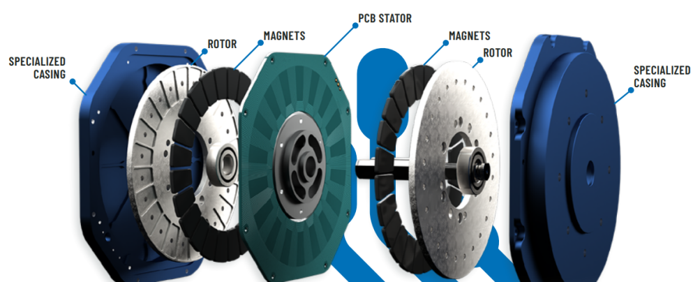
The core principle of PCB motors is based on electromagnetic induction and the Lorentz force, which enables mechanical motion through electromagnetic interaction between conductive coils on the printed circuit board and permanent magnets. Its operating principle is similar to that of traditional motors, but it features a more compact structure and flexible design. Its basic components are divided into three parts: Stator, Rotor, and Drive Circuit Stator: Composed of copper foil coils on the PCB, typically designed in specific patterns such as spiral, fan-shaped, or matrix arrangements. Rotor: Made of permanent magnets or soft magnetic materials, interacting with the stator's magnetic field to generate motion. Drive circuit: An electronic controller integrated onto the PCB or connected externally, used to regulate the timing and direction of the coil current.
Advantages of PCB Motors
1. High Efficiency and Energy SavingReduced iron loss and copper loss: PCB motors use printed circuit board coils instead of traditional wound coils, reducing eddy current losses in copper wires and hysteresis losses in the iron core, thereby significantly improving energy efficiency. For example, Infinitum Electric's latest generation of PCB stator motors achieves up to a 25% increase in efficiency.
High-frequency operation optimization: Using amorphous materials or high-permeability PCB substrates reduces iron losses during high-frequency operation, making them suitable for high-speed motor applications.
2. Lightweight and compact designFlat structure: PCB coils are directly integrated onto the circuit board, eliminating the need for traditional motor winding and iron core structures, resulting in an overall thickness as low as a few millimeters, making them suitable for space-constrained applications such as consumer electronics and drones.
Material Savings: Compared to traditional motors, PCB motors reduce the use of copper wire and silicon steel sheets, lowering weight and volume while minimizing raw material waste.
3. Manufacturing Process AdvantagesStandardized Production: Utilizing PCB manufacturing processes such as etching and lamination enables high-precision, large-scale production, reducing manual winding costs.
Automated Assembly: Some PCB motor designs support automated welding and testing, enhancing production efficiency.
4. Optimized heat dissipation performancePCB thermal conductivity advantages: Copper foil traces are directly bonded to the PCB substrate, allowing heat to be quickly dissipated through thermal holes or the metal substrate, avoiding local overheating caused by dense winding in traditional motors.
Integrated heat dissipation structure: Some designs incorporate heat dissipation fins and fans around the PCB to further enhance heat dissipation capabilities.
5. High Integration and Intelligent ControlIntegrated Drive Circuitry: The PCB can simultaneously accommodate motor windings and control circuits, reducing external wiring and improving system reliability.
EMC Performance Optimization: Through reasonable PCB layout, electromagnetic interference (EMI) can be reduced, improving signal integrity.
6. Environmental Sustainability and SustainabilityReduced carbon footprint: Production processes minimize the use of copper wire and iron cores, reducing energy consumption and waste, aligning with green manufacturing trends.
Long lifespan and maintenance-free: Brushless design eliminates carbon brush wear, extending service life.
PCB Motor Typical Problem Case Analysis and Solutions
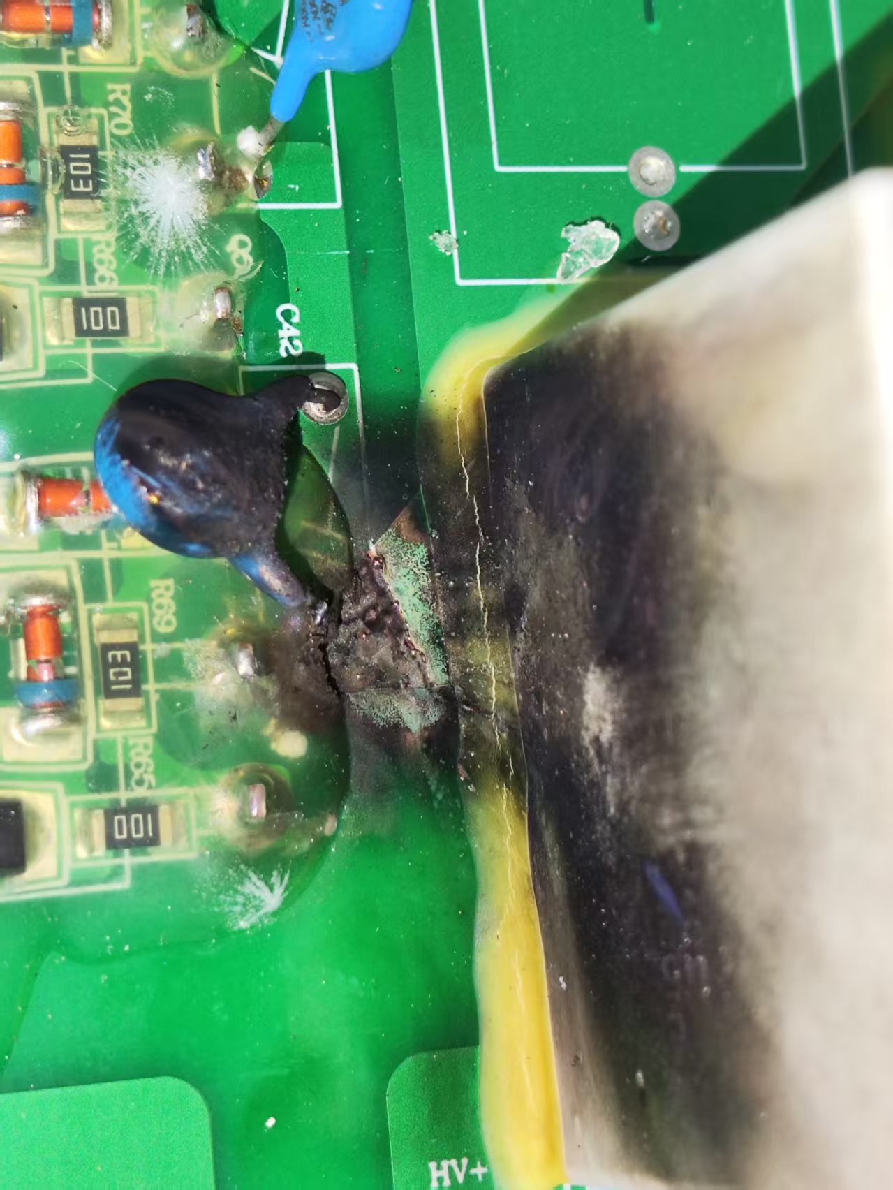
1. Poor heat dissipation leads to performance degradationIn practical applications, PCB motors often experience performance issues due to inadequate heat dissipation design. For example, a certain PCB brushless motor used in drone ESCs experienced a sudden drop in output power during prolonged high-load operation, and even resulted in the burnout of the drive IC. The root cause lies in the PCB motor's reliance on the substrate for heat dissipation, while the multi-layer stacked structure causes heat to accumulate within the internal copper layers, making it difficult to effectively dissipate. Additionally, the MOSFETs integrated onto the PCB experience increased on-resistance at high temperatures, further exacerbating thermal runaway. To address this issue, manufacturers can use aluminum or ceramic substrates to improve thermal conductivity and design heat dissipation holes or attach external metal heat sinks on the PCB. For example, some high-end drone motors have copper blocks welded to the back to enhance heat dissipation. Additionally, optimizing the layout of the drive circuit and distributing power devices to avoid localized overheating is an effective means of improving reliability.
2. High-frequency eddy current losses affect efficiencyIn industrial automation equipment, PCB linear motors may experience a sudden drop in efficiency during high-speed operation, with measured eddy current losses accounting for over 15%. This is due to high-frequency PWM signals (e.g., above 20 kHz) causing significant eddy current effects in the copper foil, while the dielectric losses of traditional FR4 substrates further exacerbate this issue. To reduce eddy current losses, ultra-thin copper foil (e.g., 12μm thickness) can be used, combined with a segmented coil design to block eddy current paths. Additionally, high-frequency-specific substrates (e.g., Rogers RO4003C) can significantly reduce dielectric losses. Some precision devices also apply magnetic coatings to the PCB surface to suppress high-frequency magnetic field leakage, thereby improving overall efficiency.
3. Structural failure caused by insufficient mechanical strengthWhen flexible PCB motors are used in wearable devices, repeated bending may cause coil fractures, resulting in abnormally high resistance values. Ordinary electrolytic copper foil has poor ductility and is prone to cracking after more than 500 bends. Insufficient bonding strength between the substrate and copper layer also accelerates failure. Improvement measures include replacing electrolytic copper foil with rolled copper foil, which has better fatigue resistance; or adding flexible adhesive between the copper foil and substrate to enhance bonding strength. Additionally, optimizing the coil routing design to avoid right-angle turns and using serpentine or curved routing can significantly improve bending lifespan. For example, the vibration motor in a certain TWS earbud achieved over 100,000 bending cycles through serpentine routing design.
4. Electromagnetic interference (EMI) affecting sensitive devicesIn medical devices, high-frequency noise generated by PCB motors during operation may interfere with electrocardiogram monitoring signals, causing noise in the waveform. This issue typically stems from rapid switching actions in the motor drive circuit, with noise propagating through spatial radiation or power line conduction to sensitive circuits. If PCB layout does not consider EMC design—such as parallel routing of power lines and signal lines—interference will be further exacerbated. Solutions include wrapping the motor with a copper foil shielding layer or using magnetic shielding materials to isolate the magnetic field; simultaneously, a π-type filter is added at the input end of the drive circuit, such as a series common-mode inductor to suppress conducted noise. Some high-end medical devices also employ differential signal transmission and optical isolation technology to completely block noise paths.
5. Assembly tolerances causing vibration and noiseIn the hub motors of robotic vacuum cleaners, if the assembly tolerance between the PCB stator and the permanent magnet rotor exceeds 0.1mm, it may produce a “humming” noise during low-speed operation. This is due to uneven air gaps causing magnetic field imbalance, leading to torque pulsation and vibration. Improvement measures include adopting a self-aligning bearing structure to ensure the concentricity of the rotor and stator; simultaneously introducing harmonic suppression technology into the control algorithm, such as third-harmonic compensation in field-oriented control, to smooth torque output. A certain manufacturer reduced noise by over 15 dB through optimized assembly processes and algorithm adjustments.
6. Insufficient environmental adaptability leading to failuresPCB motors used in outdoor applications may experience insulation failure in humid environments, resulting in short circuits and burnouts. The insulation resistance of standard FR4 substrates decreases significantly when exposed to moisture, and the absence of protective coating on the coil surfaces accelerates c1orrosion. Solutions include selecting substrate materials with enhanced moisture resistance and applying a three-proof coating (moisture-proof, salt fog-proof, and mold-proof) to the entire motor. In extreme environments, encapsulation processes can be used to completely seal the motor, isolating it from moisture and contaminants. A certain photovoltaic cleaning robot manufacturer extended the motor's lifespan in humid and hot environments from six months to over five years through encapsulation treatment.
7. Solder joint fatigue leading to connection failureIn vibration energy harvesting devices, solder joints between PCB coils and external wires may fracture after 100,000 vibrations. Traditional SAC305 solder lacks the necessary toughness to withstand high-frequency mechanical stress, and the absence of strain relief design further exacerbates the problem. Improvement measures include using high-ductility solder or replacing solder with conductive silver paste; additionally, adding copper pillars around the solder joints or using flexible printed circuits (FPC) jumpers to distribute stress. A certain vibration energy harvesting device achieved a vibration lifespan exceeding 500,000 cycles by optimizing solder joint design and material selection.
In the future, with the further development of PCB technology and new materials, PCB motors are expected to play a key role in more high-precision, high-demand scenarios, driving motor technology toward greater efficiency and intelligence.
One-Stop HDI PCB Manufacturer and Its PCB Via Filing Capabilities
If you're looking for turnkey HDI electronics manufacturing services (EMS) from hardware development to PCBA fabrication and box-build assembly, you can work with the one-stop HDI PCBA manufacturer PCBONLINE.
Founded in 1999, PCBONLINE has R&D capabilities for HDI projects and EMS manufacturing capabilities, including via filling for stacked vias. It provides 4-to-64-layer HDI PCB fabrication, assembly, and PCBA box-build assembly. You can order various HDI PCBs from PCBONLINE, such as FR4, polyimide (flexible PCB), polyimide + FR4 (rigid-flex PCB), and PTFE/Rogers (high-frequency PCB).

3000m² of production capacity per day for HDI PCBs with builds of 1+N+1, 2+N+2, 3+N+3,4+N+4, and arbitrary interconnection in any layers.
PCBONLINE has hardware and software R&D capabilities for IoT applications requiring HDI design, including PCBA and enclosures.
We can manufacture complex PCBs with stacker vias, via-in-pad, microvias, inlay boards, heavy copper designs, and hybrid and fine structure lay-ups.
Besides HDI PCB fabrication, we have powerful capabilities in fine-pitch assembly for HDI PCB assembly.
We have rich R&D and manufacturing experience for HDI applications such as FPGA boards.
High-quality HDI PCB and PCBA manufacturing certified with ISO 9001:2015, IATF 16949, RoHS, REACH, UL, and IPC-A-610 Class 2/3.
Here'e the PCB via filing capabilities at PCBONLINEL:
- Micriavia filling with copper: laser via size 0.1-0.125mm, priority 0.1mm
- Finished hole size for via-in-pad filling with resin: 0.1-0.9mm (drill size 0.15-1.0mm), 0.3-0.55mm normal (drill size 0.4-0.65mm)
- Max aspect ratio for via-in-pad filling with resin PCB - 12: 1
- Min resin plugged PCB thickness: 0.2mm
- Max via-filling ith resin PCB thickness: 3.2mm
- Making different hole sizes with via filling in one board: Yes
- Via filling with copper/silver: Yes
If you need HDI PCBAs or any other PCBAs requiring via filling, please send your email to PCBONLINE at info@pcbonline.com. We will provide one-on-one engineering support to you.
Conclusion
Via filling is used for creating stacked vias in HDI PCB fabrication, BGA/CSP/QFN IC packaging, and filling PCB via-in-pad with resin during multilayer PCB fabrication. If you need one-stop electronics manufacturing for your HDI PCBA project, contact the one-stop advanced PCB manufacturer PCBONLINE for high-quality PCBA and box-build solutions tailored to your project's needs.
PCB fabrication at PCBONLINE.pdf


