
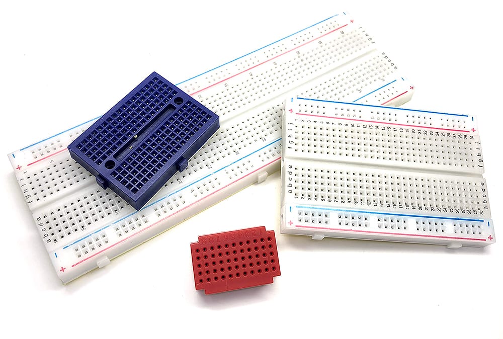
For electronics enthusiasts and professionals alike, the value of breadboards lies not only in their ability to connect components, but also in what they represent: accessibility and rapid prototyping in electronics design. Whether for simple circuit testing or complex prototype design, breadboards continue to play an irreplaceable role.
In this article:
Part 1. Proof of Concept Part 2. Interactive Debugging Part 3. Subsystem Integration Testing Part 4. Specific Examples of Breadboards Used in ScenariosProof of Concept
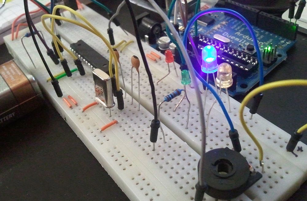
When a novel circuit concept takes shape in an engineer's mind or simulation software, its behavior in the real physical world remains unknown. Simulation models cannot perfectly replicate all real-world noise, component tolerances, and parasitic effects. At this point, professional engineers turn to breadboards. They quickly insert chips, resistors, capacitors, and sensors into the array of holes, constructing a tangible, measurable physical circuit. This process is the critical first step in transforming abstract theory into concrete reality, and any issues hidden in the simulation become immediately apparent.
Interactive Debugging
Unlike PCBs that are welded together, breadboards offer engineers unparalleled flexibility and speed thanks to their solderless design. When circuit outputs fall short of expectations, engineers can instantly plug and unplug, replace, or adjust components. They touch test points with probes, observe waveform changes on oscilloscopes, and listen to circuit responses to perform in-depth interactive debugging. This real-time iterative capability greatly compresses the development cycle. A change in resistor value, the addition of a capacitor, or a minor adjustment to a signal path can be completed in an instant, allowing engineers to focus on exploring different solutions to problems rather than getting bogged down in the manufacturing process.
Subsystem Integration Testing
In electronic systems, engineers often need to ensure that a newly designed module can work in tandem with existing commercial modules or chips. Breadboards have become the ideal platform for achieving this dialogue. For example, engineers may connect a newly designed amplifier circuit to an Arduino or Raspberry Pi to test its drive capability, or temporarily integrate a sensor array with a wireless communication module (such as Wi-Fi or Bluetooth) to verify the integrity of the data stream. The breadboard serves as a critical system integration bridge, eliminating the significant costs and time associated with designing a dedicated PCB for each test.
Specific Examples of Breadboards Used in Scenarios
1. Verifying a new sensor interface circuitMedical device engineers need to integrate a new, high-precision biosensor into their design. The sensor's output signal is extremely weak (millivolt level) and susceptible to noise interference.
The role of the breadboard: Before designing the PCB directly, the engineer built an accurate signal conditioning circuit on the breadboard. The engineer used a low-noise, high-precision operational amplifier as an instrumentation amplifier, carefully placed decoupling capacitors (as close as possible to the amplifier's power pins), and connected the sensor using shielded wires.
Why a breadboard: Engineers can quickly test different amplifier gain resistor values and experiment with various filter capacitor combinations (RC low-pass filters) to find the optimal balance between noise suppression and signal integrity. They can also use an oscilloscope to monitor signal quality in real-time after each modification. If a PCB were used directly, each modification would require at least a week of prototyping wait time and hundreds of dollars in costs.
2. Rapid prototyping of “proof-of-concept” functionality for microcontrollersEmbedded system engineers need to evaluate a specific built-in feature of a new 32-bit ARM microcontroller (MCU), such as whether its built-in digital-to-analog converter (DAC) is capable of directly driving an audio amplifier.
The role of the breadboard: The engineer connects the core board of the MCU development board (typically with 2.54mm pin spacing) to the breadboard via header pins. He then builds a simple RC filter circuit on the breadboard (to convert the DAC's square wave output into a smooth sine wave) and connects a small audio power amplifier chip (such as the LM386) and a speaker.
Why a breadboard: This provides a quick and nearly cost-free method to “feel” and test the chip's performance. Engineers can immediately hear the audio quality of the DAC's output, determine if there is audible noise or distortion, and decide whether to adopt this solution in the final design or add an external high-performance DAC chip. The entire evaluation process can be completed in a few hours.
3. Debugging and reverse engineering existing circuitsAn engineer responsible for product maintenance faced a challenge: a specialized chip on a batch of older products had been discontinued, and an alternative solution was needed.
The role of the breadboard: The engineer first used a logic analyzer to capture the input and output signals of the original chip during normal operation. Then, he used a general-purpose microcontroller (such as Arduino or STM32) on the breadboard to simulate the functionality of the specialized chip. He writes a program to have the MCU read the input signals from the original circuit, then outputs corresponding signals according to the captured logic rules to drive the subsequent circuit.
Why a breadboard: The breadboard serves as a flexible “hardware simulator.” He can continuously adjust the MCU's program and circuit connections to test in real-time whether the alternative solution can make the original device function normally. Once validated on the breadboard, he can design a PCB for an alternative module based on this solution or solidify the program into a dedicated chip.
An engineer designed an environmental monitoring station that includes analog temperature and humidity sensors, a digital LoRa wireless communication module, and a microcontroller.
Role of the breadboard: Before soldering all these modules of different natures onto a final PCB, the engineer performs system integration on the breadboard. He connects the analog outputs of the sensors to the MCU's ADC pins, connects the MCU's serial port (UART) to the LoRa module, and ensures that all devices share a common ground and that power decoupling is adequate.
Why a breadboard: This allows system integration issues to be identified in advance, such as: Does the sudden current generated by the LoRa module when transmitting signals cause a voltage drop in the power supply, thereby affecting the accuracy of analog sensor readings? Does noise from digital modules couple into analog circuits? On a breadboard, engineers can easily insert additional filter circuits or use ferrite beads to isolate digital and analog sections, thereby finding solutions.
In summary, breadboards are the most basic yet crucial tools in the field of electronic engineering, and their value goes far beyond simple circuit assembly. They serve as the first bridge between abstract theory and physical reality, and also function as a dynamic experimental platform for engineers to conduct rapid iteration, in-depth debugging, and system integration. From verifying the processing of weak signals from sensor interfaces to simulating complex chip functions to address supply chain crises, breadboards, with their unparalleled flexibility and immediate feedback, significantly reduce development risks and costs, accelerating the innovation process from concept to product.
One-Stop HDI PCB Manufacturer and Its PCB Via Filing Capabilities
If you're looking for turnkey HDI electronics manufacturing services (EMS) from hardware development to PCBA fabrication and box-build assembly, you can work with the one-stop HDI PCBA manufacturer PCBONLINE.
Founded in 1999, PCBONLINE has R&D capabilities for HDI projects and EMS manufacturing capabilities, including via filling for stacked vias. It provides 4-to-64-layer HDI PCB fabrication, assembly, and PCBA box-build assembly. You can order various HDI PCBs from PCBONLINE, such as FR4, polyimide (flexible PCB), polyimide + FR4 (rigid-flex PCB), and PTFE/Rogers (high-frequency PCB).

3000m² of production capacity per day for HDI PCBs with builds of 1+N+1, 2+N+2, 3+N+3,4+N+4, and arbitrary interconnection in any layers.
PCBONLINE has hardware and software R&D capabilities for IoT applications requiring HDI design, including PCBA and enclosures.
We can manufacture complex PCBs with stacker vias, via-in-pad, microvias, inlay boards, heavy copper designs, and hybrid and fine structure lay-ups.
Besides HDI PCB fabrication, we have powerful capabilities in fine-pitch assembly for HDI PCB assembly.
We have rich R&D and manufacturing experience for HDI applications such as FPGA boards.
High-quality HDI PCB and PCBA manufacturing certified with ISO 9001:2015, IATF 16949, RoHS, REACH, UL, and IPC-A-610 Class 2/3.
Here'e the PCB via filing capabilities at PCBONLINEL:
- Micriavia filling with copper: laser via size 0.1-0.125mm, priority 0.1mm
- Finished hole size for via-in-pad filling with resin: 0.1-0.9mm (drill size 0.15-1.0mm), 0.3-0.55mm normal (drill size 0.4-0.65mm)
- Max aspect ratio for via-in-pad filling with resin PCB - 12: 1
- Min resin plugged PCB thickness: 0.2mm
- Max via-filling ith resin PCB thickness: 3.2mm
- Making different hole sizes with via filling in one board: Yes
- Via filling with copper/silver: Yes
If you need HDI PCBAs or any other PCBAs requiring via filling, please send your email to PCBONLINE at info@pcbonline.com. We will provide one-on-one engineering support to you.
Conclusion
Via filling is used for creating stacked vias in HDI PCB fabrication, BGA/CSP/QFN IC packaging, and filling PCB via-in-pad with resin during multilayer PCB fabrication. If you need one-stop electronics manufacturing for your HDI PCBA project, contact the one-stop advanced PCB manufacturer PCBONLINE for high-quality PCBA and box-build solutions tailored to your project's needs.
PCB fabrication at PCBONLINE.pdf


