
Gerber files are necessary documentation for printed circuit board (PCB) fabrication. When you draw the schematics, you need to make them Gerber files so that PCB manufacturers can follow your requirements.
You may ask, what is a Gerber file?
More importantly, how to generate Gerber files?
No worries, this post will let you know what is Gerber, how to create a Gerber file, and how to print PCBs from the Gerber file.
Part 1: What is a Gerber File
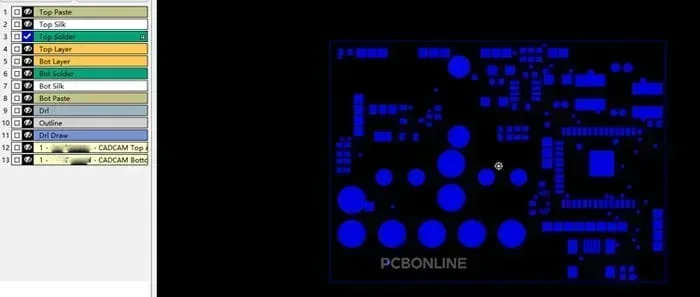
The Gerber format is an open 2D binary vector image file format. A Gerber file is the standard file used by printed circuit board industry software to describe the PCB images such as copper layers, solder masks, legends, etc.
Each layer of the PCB needs a Gerber file.
When you generate Gerber files for either a single-layer or a multilayer PCB, multiple Gerber files are saved at once in an RAR or ZIP file.
Gerber Files by Type and FormatThe trick with Gerbers is that every file you generate will be associated with a particular layer on your board layout, each with its unique file extension.
File Extension of PCB Layer on Autodesk EAGLE
|
File Extension
|
PCB Layer
|
|---|---|
|
.cmp
|
Top Copper
|
|
.sol
|
Bottom Copper
|
|
.stc
|
Top Soldermask
|
|
sts
|
Bottom Soldermask
|
|
.plc
|
Top Silkscreen
|
|
.pls
|
Bottom Silkscreen
|
File Extension of PCB Layer on Altium Designer
|
File Extension
|
PCB Layer
|
|---|---|
|
.GTO
|
Top Overlay
|
|
.GTP
|
Top Paste
|
|
.GTP1
|
Top Paste
|
|
.GTS1
|
Top Solder
|
|
.GTS
|
Top Solder
|
|
.GTL
|
Top Layer
|
|
Top Layer
|
<2-11
|
|
.G1
|
Mid-Layer 1
|
|
.G2
|
Mid-Layer 2
|
|
.GBL
|
Bottom Layer
|
|
.GBS
|
Bottom Solder
|
|
.GBP
|
Bottom Paste
|
|
.GBO
|
Bottom Overlay
|
|
.GM1
|
Mechanical 1
|
|
.GM7
|
Mechanical 7
|
|
.GM13
|
Mechanical 13
|
|
.GM15
|
Mechanical 15
|
|
.GM16
|
Mechanical 16
|
|
.GKO
|
Keep-Out Layer
|
|
.GPT
|
Top Pad Master
|
|
.GPB
|
Bottom Pad Master
|
Another thing to remember about Gerber's is their available formats – Gerber RS-274D and Gerber RS-274X. The D format is the older standard and uses two files per layer on your PCB. The newer X standard has done away with the two file formats and contains all of the information about a layer in a single file.
Regarding having to manage your design data, the X format makes it a whole lot easier when you only have to keep track of one file per layer instead of two. We'd always recommend using the Gerber RS-274X format.
Now you've got to know that once you generate Gerber files, you can get the PCB printed from them. Let's dive to see how to generate Gerber files using OrCAD and Altium!
Part 2: Creating a Gerber File Using OrCAD
Step 1. First of all, design a PCB on any OrCAD software (like in the figure below ). To learn more about PCB layout, read here. Verify all points to check those are not shorted. After verification, move to the next step.
![]()
Step 2. Navigate to the "Output" option on the top tab of the software.
![]()
Step 3. After clicking on "Output", choose "Generate Gerber".
![]()
Step 4. Click on "Output to a single ZIP file", and then go to "Reflection" > "Mirror". Confirm to generate a Gerber file by clicking on "OK".
![]()
Step 5. Finally, the Gerber file in ZIP format is generated. It can be found in your saved location.
![]()
Part 3: Generating Gerber Files Using Altium
Step 1. Open your schematic using Altium Designer. Navigate to the "File" option on the top tab of the software and go to "Fabrication Outputs" > "Gerber Files".
![]()
Step 2. You will jump to the Gerber Setup window. Here, you need to choose the "Layers" option on the top tab.
Step 3. Then click "Plot Layers" > "All on". Confirm to create the Gerber file by clicking the "OK" button.
![]()
If you want to generate the drill file, follow the steps below.
Step 1. Open the schematic using Altium. Navigate to the "File" option on top of the tap.
Step 2. Choose "Fabrication Outputs" and click "NC Drill Files" from the drop-down list.
![]()
Step 3. The NC Drill Setup window is open. Click "OK" and you create the drill file.
![]()
Note
The drill file and Gerber file are generated separately. But you need to place them into the same RAR or ZIP file before uploading the file on a PCB printing website.
Part 4: Applications of Gerber Files
As mentioned above, a Gerber file is a 2D binary vector image file format to describe the circuit board image. It was widely used to drive vector plotters. Details Expand in this Standard Gerber - Standard Gerber was a numerical control (NC) format designed by Gerber Systems Corp to drive their vector photo plotters for the PCB industry in the 1960s and 1970s. It was a subset of the Electronic Industries Association RS-274-D specification, a format to drive mechanical NC machines in a wide range of industries.
Send Your Gerber File for One-Stop PCB Manufacturing
PCBONLINE is a source factory manufacturer for PCB fabrication and assembly. Founded in 1999, it has two large advanced PCB manufacturing bases and one PCB assembly factory that all pass the ISO quality system certification.
At PCBONLINE, you can order PCBs, PCBA, electronic components, and box build assembly at one stop.
High-quality PCB and PCBA manufacturing certified with ISO 9001:2015, IATF 16949, REACH, UL, IPC, and RoHS.
No minimum PCB number is required for placing an order, and you can upload your Gerber to see the PCB price online.
Providing one-on-one engineering support throughout your project and optimizing your PCB design to reduce the PCB cost without quality sacrifice.
PCBONLINE has rich PCB and electronic manufacturing experience for consumer electronics and automotive, industrial, medical, aerospace, defense, telecommunication, and computing devices. If you want to work with PCBONLINE, you can send your Gerber or inquiry to info@pcbonline.com.


