
As the Internet of Things (IoT) continues to transform our everyday life, home security is becoming smarter, safer, and more accessible. Among the many innovations, the smart door lock system stands out for its practicality and value in enhancing residential and commercial security. The IoT PCBA manufacturer PCBONLINE provides this in-depth guide to building an ESP32-based smart door lock system, complete with input mechanisms, Wi-Fi capability, optional display, and PCB design considerations. The project is scalable, affordable, and serves as a stepping stone to integrating advanced IoT solutions.
Why Use ESP32 for a Smart Door Lock?
The ESP32 microcontroller is a robust and feature-rich platform ideal for smart lock projects:
- Integrated Wi-Fi and Bluetooth: Enables wireless access, control, and communication.
- Affordable and compact: Perfect for embedded applications where space and cost matter.
- Power efficiency: Low-power modes allow for battery-powered designs.
- GPIO abundance: Supports connecting multiple peripherals (keypads, displays, relays, etc.).
- Community and support: Extensive libraries and resources are available for development.
Components required:
- ESP32 Dev board
- 4x4 matrix keypad or fingerprint/RFID module
- Servo motor or dolenoid lock
- Relay module (if using solenoid lock)
- OLED Display (optional)
- Buzzer and LED (optional)
- Power supply or battery pack
- PCB and connectors for the final design
- Arduino Nano: Reads DS18B20 sensors and controls relays.
- ESP8266 NodeMCU: Publishes data to MQTT.
- DS18B20: Waterproof temperature sensor (-55°C to +125°C).
- 5V relay: Switches 220V heating mat.
- Power supply: 12V/2A adapter with buck converter (12V→5V).
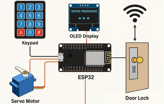
System overview
- Input mechanism: Users can input a password via a keypad or authenticate using RFID/fingerprint sensors. You can also extend the functionality to receive unlock commands over Wi-Fi or Bluetooth using a mobile app.
- Authentication: The ESP32 verifies the password or access credentials. If valid, it triggers the unlocking mechanism.
- Lock control: A servo motor rotates to unlock or lock the door. Alternatively, a relay activates a solenoid lock.
- Feedback: An OLED or LED display shows status messages, and a buzzer provides audible feedback.
- Remote access (optional): ESP32 connects to Wi-Fi, allowing users to unlock doors remotely through a web or mobile app using MQTT, Blynk, or HTTP APIs.
PCBA Applications for ESP32-Based Smart Door Lock
PCBONLINE provides PCBA (printed circuit board assembly) manufacturing for IoT like ESP32-based smart door locks used for the following applications.
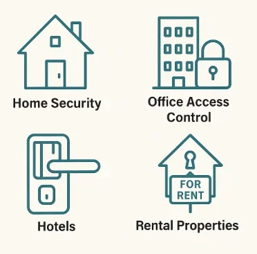
- Home security: Replace conventional locks with smarter, more secure access.
- Office access systems: Grant controlled access to employees or visitors.
- Hotel rooms: Temporary codes for guests, with logging.
- Remote gate control: Unlock gates via mobile phone.
- IoT projects: Integration with smart home platforms like Home Assistant.
- Rental properties: Time-based or app-controlled access.
- Web server interface: Host a webpage on the ESP32 to unlock remotely.
- MQTT integration: Use MQTT for cloud connectivity and monitoring.
- ESP32-CAM: Add face recognition before unlocking.
- EEPROM/flash storage: Save access logs or multiple passwords.
- Push notification: Use Telegram Bot or IFTTT to send alerts.
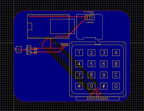
Circuit Design and Schematic Overview
The IoT PCBA manufacturer PCBONLINE has rich experience in R&D and engineering. In your circuit design for ESP32-based smart door locks, we advise these key Connections:
- Keypad: Connects to 8 GPIO pins.
- Servo motor: Connect to a PWM-capable GPIO (e.g., GPIO13).
- OLED display: Connect via I2C (SDA to GPIO21, SCL to GPIO22).
- Relay (for solenoid): Connect to a digital GPIO with transistor and diode protection.
- Buzzer/LED: Optional, for status indication.
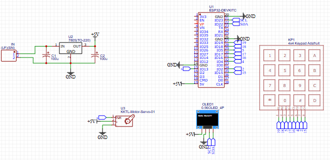
Regarding the power supply, use a 5V regulated power source. For battery operation, use Li-ion with a charging module.
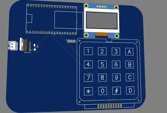
PCB Design Considerations
For a permanent and compact setup, design a custom PCB using tools like KiCad or Altium Designer.
PCBONLINE's PCB design tips
- Use screw terminals or JST connectors for modules (keypad, servo, OLED).
- Route power and GND planes carefully to minimize noise.
- Use a voltage regulator if you plan to power from a 12V adapter.
- Include headers for UART (TX, RX) for debugging.
- Use SMD components to reduce PCB size.
PCBONLINE's suggested PCB sections
- ESP32 mounting footprint
- Power management (battery and regulator)
- Relay and solenoid section
- Keypad connector block
- Display and buzzer
- Programming and debugging header
You can also include footprints for future upgrades like fingerprint or NFC modules.
Example Code Snippet: Keypad and Servo-Based Lock
#include <Keypad.h>
#include <ESP32Servo.h>
#include <Wire.h>
#include <Adafruit_GFX.h>
#include <Adafruit_SSD1306.h>
#define SCREEN_WIDTH 128
#define SCREEN_HEIGHT 64
#define OLED_RESET -1
Adafruit_SSD1306 display(SCREEN_WIDTH, SCREEN_HEIGHT, &Wire, OLED_RESET);
const byte ROWS = 4;
const byte COLS = 4;
char keys[ROWS][COLS] = {
{'1','2','3','A'},
{'4','5','6','B'},
{'7','8','9','C'},
{'*','0','#','D'}
};
byte rowPins[ROWS] = {19, 18, 5, 17};
byte colPins[COLS] = {16, 4, 2, 15};
Keypad keypad = Keypad(makeKeymap(keys), rowPins, colPins, ROWS, COLS);
Servo lockServo;
String password = "1234";
String input = "";
void setup() {
Serial.begin(115200);
lockServo.attach(13); // Servo pin
lockServo.write(0); // Locked
if(!display.begin(SSD1306_SWITCHCAPVCC, 0x3C)) {
Serial.println(F("SSD1306 allocation failed"));
while(true);
}
display.clearDisplay();
display.setTextSize(1);
display.setTextColor(SSD1306_WHITE);
display.setCursor(0,0);
display.print("Enter Password:");
display.display();
}
void loop() {
char key = keypad.getKey();
if (key) {
if (key == '#') {
if (input == password) {
displayMessage("Access Granted");
unlockDoor();
} else {
displayMessage("Access Denied");
}
input = "";
} else {
input += key;
displayEntered(input);
}
}
}
void unlockDoor() {
lockServo.write(90); // Unlock
delay(5000);
lockServo.write(0); // Lock again
displayMessage("Enter Password:");
}
void displayMessage(String msg) {
display.clearDisplay();
display.setCursor(0,0);
display.print(msg);
display.display();
delay(2000);
display.clearDisplay();
display.setCursor(0,0);
display.print("Enter Password:");
display.display();
}
void displayEntered(String entered) {
display.clearDisplay();
display.setCursor(0,0);
display.print("Enter Password:");
display.setCursor(0,20);
display.print(entered);
display.display();
}
Partner with PCBONLINE to Manufacture Your Smart Door Locks
Whether you are working on smart door locks or any other IoT projects, you can partner with PCBONLINE for printed circuit board fabrication and assembly under one roof. Besides, PCBONLINE can complete the box builds, including application testing, so that you can sell the ready-to-use smart door locks.
Foounded in 1999, PCBONLINE has two large advanced PCB manufacturing bases, one turnkey PCB assembly factory, stable material supply chains, strategic cooperation with the mainstream MCU manufacturers, long-term cooperation with the top 3 fixture and enclosure manufacturers in China, and an R&D team and professional CAM engineers for project development and DFM (design for manufacturing).

PCBONLINE offers free DFM before and during prototyping/sampling to ensure the success of mass production of your smart door locks.
PCBONLINE can provide or assist R&D for your IoT project, including hardware and software R&D, schematics, PCB design, testing design, and enclosure design.
PCBONLINE provides custom and one-stop electronics manufacturing for smart door locks, including PCB manufacturing, component sourcing, PCB assembly, IC programming, burn-in test, conformal coating, enclosures, and box-build assembly.
As a source factory PCBA manufacturer, PCBONLINE offers cost-effective manufacturing services. And when your project enters mass production, we refund the fees of R&D, prototyping and offer free PCBA functional testing.
High-quality IoT PCB/PCBA manufacturing certified with ISO 9001:2015, ISO 14001:2015, ISO 14001:2015, IATF 16949:2016, RoHS, REACH, UL, IPC-A-610 Class 2/3, and IPC-A-610 Class 2/3.
No matter what quantity you want, we always prioritize quality and provide service and support that meet and exceed your expectations.
PCBONLINE has worked on many IoT projects for our clients, including smart door locks. You can send your R&D and PCBA manufacturing request to PCBONLINE. To get a quote for your IoT project, please email info@pcbonline.com.
Conclusion
The custom ESP32-based door lock is a feature-rich and practical IoT project. With wireless connectivity, flexible input methods, and expandable design, it can be tailored for a variety of applications. Designing a custom PCB adds professionalism and reliability to the prototype. To bring your smart door lock project to life with reliability and cost-effectiveness, work with the EMS IoT PCBA manufacturer PCBONLINE.
PCB assembly at PCBONLINE.pdf


