
The Internet of Things (IoT) is a network of physical devices connected by means of the Internet to share data and communicate with each other. The devices are a combination of computers, microcontrollers, and sensors. In this article, we will discuss the IoT-based beeHives monitoring system using ESP-32.
BeeHive Monitoring System
An ESP-32 beeHives monitoring system checks condition parameters, such as temperature, humidity, weight, etc. It shows the conditions on smartphones via push notifications or mobile apps for a detailed inspection through graphs and so on.
The applications of ESP-32 beeHives monitoring systems can be used for smart home automation, kitchen appliances, car smart screens, thermostats, baby monitors, etc. A large number of sensors can be joined to such a system based on ESP32. All the data can be saved on a server or back-end and be shown on users' mobile phones.
As this is a blog, we keep it simple with respect to the sensors and the ESP32 network to show you the process of designing and electronics manufacturing for this ESP-32 beehives monitoring project. This project monitors only one hive.
Step 1. Install the system barin - ESP32
First, let's see the main component of this project - ESP32 by ESPRESSIF.
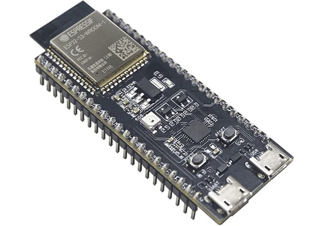
- ESP32 is a feature-rich MCU with integrated Wi-Fi and Bluetooth connectivity with low-energy consumption with a robust design.
- Ultra-low power consumption: ESP32 consumes extremely low energy as compared to the other microcontrollers.
- High level of integration: ESP32 is integrated with in-built antenna switches, RF, power amplifiers, low-noise receive amplifiers, filters, and power management modules.
- Hybrid Wi-Fi & Bluetooth chip: ESP32 can interface with other systems to provide Wi-Fi and Bluetooth functionality through its SPI / SDIO or I2C / UART interfaces.
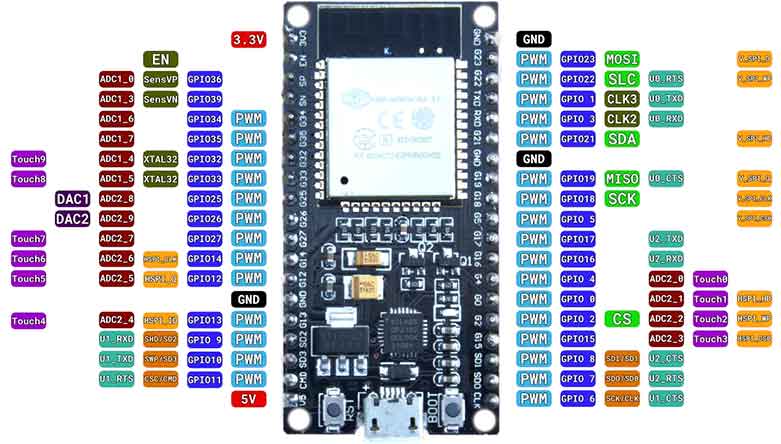
Since there are a lot of GPIO pins therefore adding more sensors will be easy.
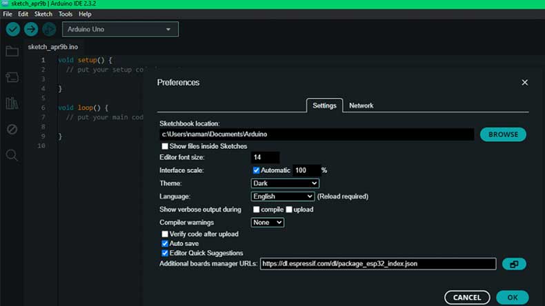
For using this board in Arduino IDE, we first install the ESP32 board from files on the top left corner of Arduino IDE and open Preferences.
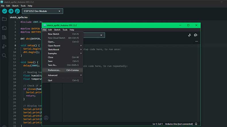
In Additional Boards Manager URLs section, paste the link: https://dl.espressif.com/dl/package_esp32_index.json
From tools, we open the board's manager, search for ESP32, and click install. Now, the installment of hardware support and all the dependencies for ESP32 starts.
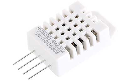
Step 2. Use the temperature and humidity sensor DHT22
Our next component of the system is the temperature and humidity sensor DHT22. It is low-cost and has a single digital interface.
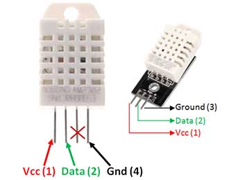
Connect the first pin on the left to 3-5V power, the second pin to your data input pin, and the rightmost pin to the ground. The pins-out diagram is shown.
Now, let's see how to use the DHT22 module with the ESP32 in Arduino IDE.
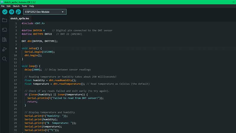
Open the Arduino, select the port from the tools on which ESP32 is attached, select the board from ESP32, and select the suitable board as your hardware. Now, click on compile, upload the code, and open the serial monitor. This will show your temperature and humidity. If you have the wrong temperature and humidity, you can calibrate it by adding or subtracting the calibration factor value in the code.
Until now, we have been getting the temperature and humidity values from the sensor and saving them to the SD card module. We are using the SD card module.
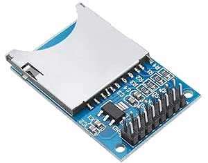
Now paste the following code in the Arduino IDE to save the temperature and humidity values to the SD card as a text file.
#include
#include
#include
#define DHTPIN 4 // Digital pin connected to the DHT sensor
#define DHTTYPE DHT22 // DHT 22 (AM2302)
DHT dht(DHTPIN, DHTTYPE);
File dataFile;
void setup() {
Serial.begin(115200);
dht.begin();
if (!SD.begin()) {
Serial.println("SD Card initialization failed!");
return;
}
Serial.println("SD Card initialized successfully!");
dataFile = SD.open("sensor_data.txt", FILE_WRITE);
if (!dataFile) {
Serial.println("Error opening file for writing!");
return;
}
}
void loop() {
delay(2000); // Delay between sensor readings
// Reading temperature or humidity takes about 250 milliseconds!
float humidity = dht.readHumidity();
float temperature = dht.readTemperature(); // Read temperature as Celsius (the default)
// Check if any reads failed and exit early (to try again).
if (isnan(humidity) || isnan(temperature)) {
Serial.println(F("Failed to read from DHT sensor!"));
return;
}
// Display temperature and humidity
Serial.print(F("Humidity: "));
Serial.print(humidity);
Serial.print(F("% Temperature: "));
Serial.print(temperature);
Serial.println(F("°C"));
// Write data to SD card
dataFile.print("Humidity: ");
dataFile.print(humidity);
dataFile.print("% Temperature: ");
dataFile.print(temperature);
dataFile.println("°C");
dataFile.flush(); // Ensure data is written to the file
delay(5000); // Delay for 5 seconds before the next reading
}
Step 3. Use a server or back-end
We need a server or back-end to save the above text file and later send the data to the mobile as a notification. Here, I am using Google Firebase as an example.
First, create an account on Firebase, click Get Started, type the project name, and check the agreement boxes to continue.

We follow the onscreen instructions and click the setting icon to open project settings.
Go to the services account and copy the key as shown.
Open Arduino IDE and use the copied key in the code. Paste the code below.
#include
#include
#include
#include
#include "esp_camera.h"
#include
#include
// WiFi credentials
#define WIFI_SSID "YourWiFiSSID"
#define WIFI_PASSWORD "YourWiFiPassword"
// Firebase credentials
#define FIREBASE_HOST "yourproject.firebaseio.com"
#define FIREBASE_AUTH "YourFirebaseAuthenticationKey"
// Sensor pin configurations
#define DHTPIN 4
#define DHTTYPE DHT22
#define SOUND_PIN 5
#define SD_CS_PIN 15
// ESP32-CAM pin configurations
#define ESP32_CAM_RX_PIN 16 // RX pin of ESP32-CAM connected to pin 16 of main ESP32
#define ESP32_CAM_TX_PIN 17 // TX pin of ESP32-CAM connected to pin 17 of main ESP32
FirebaseData firebaseData;
DHT dht(DHTPIN, DHTTYPE);
HardwareSerial ESP32_CAM_Serial(1);
void setup() {
Serial.begin(115200);
pinMode(SOUND_PIN, INPUT);
pinMode(SD_CS_PIN, OUTPUT);
if (!SD.begin(SD_CS_PIN)) {
Serial.println("SD Card initialization failed.");
return;
}
connectWiFi();
Firebase.begin(FIREBASE_HOST, FIREBASE_AUTH);
cameraInit();
ESP32_CAM_Serial.begin(115200, SERIAL_8N1, ESP32_CAM_RX_PIN, ESP32_CAM_TX_PIN);
}
void loop() {
float temperature = dht.readTemperature();
float humidity = dht.readHumidity();
int soundValue = analogRead(SOUND_PIN);
saveDataToSDCard(temperature, humidity, soundValue);
captureAndSendImage();
sendDataToFirebase(temperature, humidity, soundValue);
notifyMobileApp(temperature, humidity, soundValue);
delay(5000); // Adjust delay according to your requirement
}
void connectWiFi() {
WiFi.begin(WIFI_SSID, WIFI_PASSWORD);
Serial.print("Connecting to Wi-Fi");
while (WiFi.status() != WL_CONNECTED) {
Serial.print(".");
delay(500);
}
Serial.println();
Serial.print("Connected to Wi-Fi: ");
Serial.println(WiFi.localIP());
}
void saveDataToSDCard(float temperature, float humidity, int soundValue) {
File dataFile = SD.open("data.txt", FILE_WRITE);
if (dataFile) {
dataFile.println("Temperature: " + String(temperature) + "°C");
dataFile.println("Humidity: " + String(humidity) + "%");
dataFile.println("Sound Level: " + String(soundValue));
dataFile.close();
} else {
Serial.println("Error opening data.txt file.");
}
}
void sendDataToFirebase(float temperature, float humidity, int soundValue) {
Firebase.pushFloat(firebaseData, "/temperature", temperature);
Firebase.pushFloat(firebaseData, "/humidity", humidity);
Firebase.pushInt(firebaseData, "/sound", soundValue);
}
void cameraInit() {
camera_config_t config;
config.ledc_channel = LEDC_CHANNEL_0;
config.ledc_timer = LEDC_TIMER_0;
config.pin_d0 = Y2_GPIO_NUM;
config.pin_d1 = Y3_GPIO_NUM;
config.pin_d2 = Y4_GPIO_NUM;
config.pin_d3 = Y5_GPIO_NUM;
config.pin_d4 = Y6_GPIO_NUM;
config.pin_d5 = Y7_GPIO_NUM;
config.pin_d6 = Y8_GPIO_NUM;
config.pin_d7 = Y9_GPIO_NUM;
config.pin_xclk = XCLK_GPIO_NUM;
config.pin_pclk = PCLK_GPIO_NUM;
config.pin_vsync = VSYNC_GPIO_NUM;
config.pin_href = HREF_GPIO_NUM;
config.pin_sscb_sda = SIOD_GPIO_NUM;
config.pin_sscb_scl = SIOC_GPIO_NUM;
config.pin_pwdn = PWDN_GPIO_NUM;
config.pin_reset = RESET_GPIO_NUM;
config.xclk_freq_hz = 20000000;
config.pixel_format = PIXFORMAT_JPEG;
if (psramFound()) {
config.frame_size = FRAMESIZE_UXGA;
config.jpeg_quality = 10;
config.fb_count = 2;
} else {
config.frame_size = FRAMESIZE_SVGA;
config.jpeg_quality = 12;
config.fb_count = 1;
}
esp_err_t err = esp_camera_init(&config);
if (err != ESP_OK) {
Serial.printf("Camera init failed with error 0x%x", err);
return;
}
}
void captureAndSendImage() {
camera_fb_t *fb = esp_camera_fb_get();
if (!fb) {
Serial.println("Camera capture failed");
return;
}
File file = SD.open("/image.jpg", FILE_WRITE);
if (!file) {
Serial.println("Failed to open file for writing");
return;
}
file.write(fb->buf, fb->len);
file.close();
esp_camera_fb_return(fb);
Serial.println("Image captured and saved to SD card");
}
void notifyMobileApp(float temperature, float humidity, int soundValue) {
HTTPClient http;
// Construct the URL with Firebase data
String firebaseURL = "https://" + String(FIREBASE_HOST) + "/.json";
// Make a GET request to fetch Firebase data
http.begin(firebaseURL);
int httpCode = http.GET();
if (httpCode == HTTP_CODE_OK) {
String payload = http.getString();
DynamicJsonDocument doc(1024);
DeserializationError error = deserializeJson(doc, payload);
if (error) {
Serial.println("Failed to parse Firebase data");
return;
}
float latestTemperature = doc["temperature"];
float latestHumidity = doc["humidity"];
int latestSoundValue = doc["sound"];
// Compare latest data with current data
if (latestTemperature > temperature || latestHumidity > humidity || latestSoundValue > soundValue) {
// Notify mobile app with notification message
String notificationMessage = "Alert: Abnormal conditions detected";
// You need to implement mobile app notification mechanism here
// This can be achieved using Firebase Cloud Messaging (FCM) or similar services
Serial.println("Notification sent to mobile app");
}
} else {
Serial.println("Failed to fetch Firebase data");
}
http.end();
}
Step 4. Communication between ESP32 and ESP32-CAM
The communication between the ESP32 modules uses serial communication (UART). Here are some ways to implement this.
Define UART Pins: For UART communication, choose two GPIO pins on both the main ESP32 board and the ESP32-CAM module. You'll need to connect these pins physically.
Initialize serial communication: In the setup function of both ESP32 boards, initialize Serial communication using the Serial.begin() function. Specify the baud rate (e.g., 115200) that both modules will use for communication.
Send data (Main ESP32): In the main ESP32 board's code, when you want to send data to the ESP32-CAM, use the Serial.print() or Serial.write() function to send data over the serial connection.
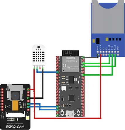
The above circuit has been created in Fritzing showing only the connection of ESP32 and the sensors.
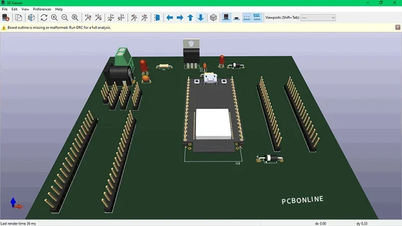
PCB for the BeeHive Monitoring System
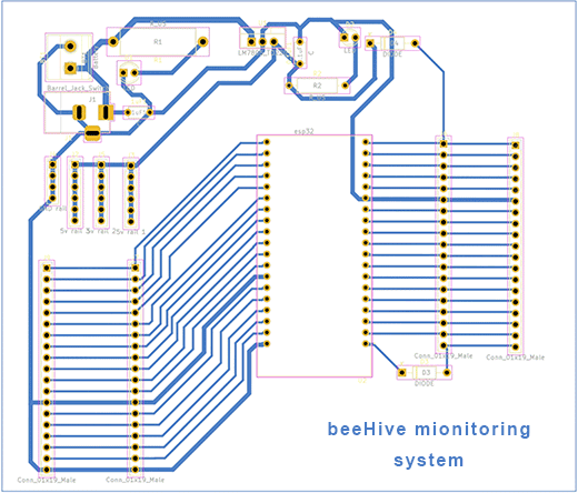
The PCB has been created in KiAD 7.0 Software. The routing is in a single layer. The power section has a voltage regulator circuit with filter capacitors. A DC input jack is used for power input from power or other DC voltage soures.
The Gerber file is attached at the end of the blog. You can upload it to PCBONLINE's online quote page for PCB manufacturing.
Apart from the ESP32, ESP32-CAM, and DHT22, the other components of the PCB are below.
|
Components
|
Description
|
Quantity
|
|
DC Jack
|
---
|
1
|
|
T-block
|
---
|
1
|
|
Resistor
|
330Ω
|
4
|
|
Capacitor
|
0.1 nf
|
5
|
|
Diode
|
---
|
2
|
|
LED
|
---
|
2
|
|
Header pin
|
Male
|
4 (20pins)
|
|
LM7805
|
---
|
1
|
This ESP-32 beeHive project can be further improved by adding a weight sensor, like load cells with an ADC HX 711. The data from Firebase can be used to train an AI model for automatic disease detection.
One-Stop Electronics Manufacturing for ESP-32 BeeHive Systems and IoT Devices
To turn the above ESP-32 beeHive system and the other IoT projects into real products, you can work with the one-stop electronics manufacturing service (EMS) provider PCBONLINE, covering PCB fabrication, component sourcing, PCB assembly, IC programming, enclosures, and final product box-build assembly.
Founded in 1999, PCBONLINE has two large advanced PCB manufacturing bases, one PCB assembly factory, and an R&D team with rich IOT R&D and engineering experiences.

You can have electronics manufacturing for ESP-32 beeHive systems and IoT devices under one roof from prototypes to bulk production.
The engineers from PCBONLINE have strong R&D and manufacturing capabilities to meet all your design demands.
PCBONLINE has strategic cooperation with Espressif and can source more affordable ESP-32 chips and modules.
Relying on its EMS PCB assembly factory, PCBONLINE can take part in co-procurement with other large EMS from original component factories.
Traceable and high-quality PCBA manufacturing certified with ISO 9001:2015, IATF 16949, RoHS, REACH, UL, and IPC-A-610 Class 2/3.
Once you contact PCBONLINE, we will offer you one-on-one engineering support throughout your project. To get reliable electronics manufacturing that meets your custom demands, please email PCBONLINE at info@pcbonline.com.
Conclusion
ESP-32 beeHive systems can be used for a wide range of IoT applications. This blog shows the design process of a simple ESP-21 beeHiave monitoring system step by step. It is okay for hobbyists to solder the boards at home, but for original equipment manufacturers, business makers, and research institutes, for high quality, work with a professional PCBA source factory manufacturer, PCBONLINE, for one-stop electronics manufacturing is the best option.
Attached Gerber and PCBA capability PDFbeeHive system PCB Gerber.rar
PCB assembly at PCBONLINE.pdf


