

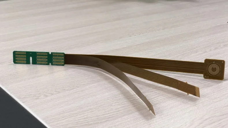
A rigid-flex PCB and a flexible PCB with stiffeners bonded to selected regions are two constructions that fit into a compact enclosure. The two PCBs may sometimes look alike, but their stack-up, process, bend life, and cost are different.
This article concisely compares a rigid-flex PCB and a flexible PCB with stiffeners concisely. PCBONLINE fabricates rigid-flex and flexible PCBs in-house, from FR4, PI, and stainless steel stiffeners for FPC to HDI rigid-flex PCBs up to 4+N+4. For EV battery pack projects, we also build FDC interconnects for the CCS and customize pierce-crimp terminals for the connectors.
What Is a Rigid-Flex PCB?
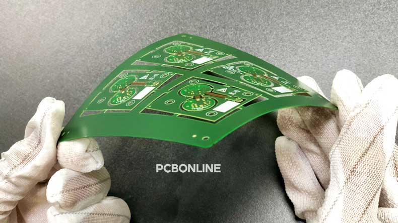
A rigid-flex PCB combines flexible polyimide circuits and rigid FR4 sections into a single laminated PCB. The internal core of a rigid-flex PCB is a continuous flexible circuit. FR4 outer layers cover the top and bottom of the rigid zones, while the flex zones stay exposed and free to bend.
At PCBONLINE, we manufacture rigid-flex PCBs in one continuous flow:
- 1. We fabricate the flexible PI circuit first as the inner layer, using rolled-annealed copper on polyimide.
- 2. We laminate FR4 outer PCB layers onto the top and bottom of the rigid zones.
- 3. We laser-cut from the outermost rigid layer down to the inner flex layer, removing only the copperless FR4 in the unused regions.
- 4. The exposed polyimide region becomes the bending zone of the finished PCB.
The flexible layers run through the entire PCB, so a rigid-flex PCB is fundamentally a flex circuit with rigid FR4 reinforcement in selected areas. The rigid sections sit on the outer layers, while the inner layers carry the polyimide and copper flex core.

Unlike flexible PCBs, rigid-flex PCBs use PI, never PET. The reason is that, the flexible sections in a rigid-flex PCB must withstand the high temperatures and pressure of FR4 lamination. PET film melts and degrades under lamination heat, so it cannot survive the process. Polyimide stays stable at lamination temperature, bonds reliably to FR4 prepreg, and provides the dynamic bend endurance the product needs.
Rigid-flex PCB advantages
Rigid-flex PCBs offer advantages that a stiffened FPC cannot match:
- Embedded interconnection. Vias and traces can run from the rigid section into the flex section without connector interfaces, which cuts assembly steps and improves signal integrity.
- Dynamic bending. The flex region is a true continuous flex circuit, so it can survive repeated bending in medical devices, wearables, and industrial hinges.
- Cleaner assembly. The rigid zones provide stable SMT platforms, while the flex tail routes signals into tight spaces. One PCB replaces a rigid PCB plus a cable.
- HDI capability. PCBONLINE builds rigid-flex PCBs with HDI 4+N+4 stack-ups, including blind, buried, and stacked microvias for dense routing.
What Is a Flexible PCB with Stiffener?

A flexible PCB with a stiffener has rigid material bonded over one or more areas. The rest of the circuit remains flexible, so the FPC still folds or bends where it needs to. Stiffeners sit outside the electrical layer stack and do not change the circuit.
Why add a stiffener to an FPC? Stiffeners solve three practical problems on flex circuits:
- Component mounting. Thin FPC film cannot hold large components or withstand the insertion force of connectors. A stiffener behind the component area turns that local zone into a stable platform.
- Connector durability. Plugs, ZIF connectors, and through-hole connectors need a rigid backing so the solder joints or crimp contacts do not flex during mating cycles.
- Mounting stability. Screws, standoffs, or adhesive fixtures need a flat, rigid surface that stays flat under load.
The flexible PCB still bends between the device body and the connector, while the connector area stays flat and strong.
FPC stiffener materials
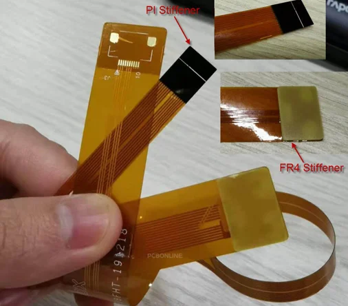
PCBONLINE offers three stiffener materials for FPC, each with different cost and performance:
|
Stiffener material
|
Typical thickness
|
Bonding method
|
Key properties
|
Best for
|
|
FR4
|
0.10–2.00 mm
|
Thermoset adhesive
|
Low cost, good peel strength, rough cut edges
|
General products
|
|
PI (Polyimide)
|
0.025–0.20 mm
|
Thermoset adhesive
|
High peel strength, precise outline
|
Space-constrained designs, tight outline tolerances
|
|
Stainless steel
|
0.15–0.30 mm
|
Adhesive or mechanical
|
High strength, excellent flatness
|
Heavy connectors, repeated mating
|
FR4 stiffeners cost the least, but the punched edges can carry burrs that affect outline precision.
PI stiffeners offer a cleaner outline and better dimensional accuracy, so engineers use PI when the stiffener must match a tight enclosure.
Stainless steel provides the highest mechanical strength and is the right choice for connectors that see frequent insertion cycles or heavy vibration.
Limits of FPC with stiffener
We bond the stiffener onto a finished FPC, and the bond line can delaminate under stress. The transition between the stiffened region and the flexible region is abrupt, so the bend must happen away from the bond line.
If the design needs repeated dynamic bending close to a component area, or if the rigid and flexible sections must share embedded vias, a stiffened FPC is reliable enough.
Rigid-Flex vs Flexible PCB with Stiffener
|
Factor
|
Flexible PCB with stiffener
|
Rigid-flex PCB
|
|
Construction
|
FPC + bonded stiffener on local areas
|
Flexible PI core laminated with FR4 rigid sections
|
|
Flex material
|
PI or PET
|
PI only
|
|
Layer count
|
1–6 layers
|
2–30+ layers, including HDI 4+N+4
|
|
Interconnection
|
Connector or solder joint between the rigid and flex sections
|
Vias route directly between rigid and flex zones
|
|
Bend performance
|
Static or low-cycle bending in the exposed tail
|
Dynamic bending over thousands or millions of cycles
|
|
Component mounting
|
Good on stiffened local areas
|
Excellent on integrated rigid zones
|
|
Thickness control
|
Stiffener adds local thickness only
|
Full control of rigid thickness and flex thickness across the whole PCB
|
|
Assembly steps
|
FPC fabrication + stiffener bonding + connector assembly
|
One integrated PCB, fewer connectors and cables
|
|
Unit cost
|
Lower for simple designs
|
Higher for simple designs, often lower at system level
|
|
Lead time
|
Shorter
|
Longer due to lamination and laser routing
|
Cost comparison
For a 4-layer design with one connector area, an FPC with an FR4 stiffener is usually cheaper than a rigid-flex PCB. The FPC process is faster and does not require the lamination, laser routing, and plating steps of rigid-flex manufacturing.

For a product with multiple rigid zones, high-speed signals, or repeated dynamic bending, rigid-flex often wins on total system cost. It eliminates connectors, cables, and separate assembly operations. The PCB unit cost is higher, but the bill of materials and labor costs drop.
At PCBONLINE, rigid-flex PCBs typically cost 2–3 times more than flexible PCBs of the same layer count and area, while FPC with stiffener sits between the two. A 0.1 square meter 4-layer PCB might cost about 900 for rigid-flex, 450 for flexible, and $100 for FR4.
Reliability comparison
The main reliability difference is the interface. On a stiffened FPC, the stiffener and the circuit meet at an adhesive bond line that can delaminate under repeated stress. The connector between the stiffened area and the flexible tail is also a fatigue point.
Rigid-flex PCBs eliminate these interfaces. The rigid and flex sections are one continuous laminate. Vias pass through the entire stack, so electrical paths do not depend on connector solder joints. For products that need long service life under vibration or repeated bending, rigid-flex is the safer choice.
When to Choose Rigid-flex PCB and FPC with Stiffener
Choose a flexible PCB with stiffener when:
- The design has one or two connector or component areas that need local support.
- The flex tail remains mostly static or sees only occasional bending.
- Cost is a primary driver, and the product has a short life cycle or consumer-grade reliability.
- The layer count is low, and signal integrity requirements are moderate.
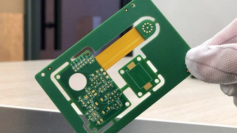
Choose a rigid-flex PCB when:
- The design needs multiple rigid zones connected by a dynamic flex section.
- The product must survive repeated bending over its full life cycle.
- High-speed signals must pass between rigid and flex regions without connectors.
- Space constraints rule out separate cables or connectors.
- The product serves medical, aerospace, automotive, or industrial markets where failure is expensive.
PCBONLINE Capabilities for FPC Stiffeners and Rigid-Flex PCBs
PCBONLINE fabricates stiffened FPCs and rigid-flex PCBs in-house, so you do not need to source a stiffener supplier separately or coordinate between FPC and rigid PCB vendors.
FPC with stiffener
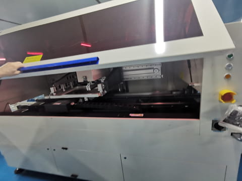
We bond FR4, PI, and stainless steel stiffeners to single-sided, double-sided, and multilayer FPCs. Our stiffener thickness ranges cover:
- FR4: 0.10–2.00 mm
- PI: 0.025–0.20 mm
- Stainless steel: 0.15–0.30 mm
We select the material based on your component load, connector type, outline tolerance, and cost target. For connector regions that see repeated mating, we recommend PI or stainless steel to avoid edge delamination.
Rigid-flex PCBs
Our Jiangsu manufacturing base operates flexible PCB lines, FR4 rigid PCB lines, and laser routing equipment in the same factory. Our rigid-flex PCB capabilities include:
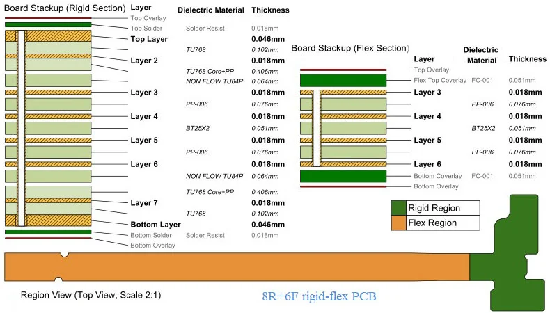
- 2 to 30 layers
- HDI 4+N+4 with blind, buried, staggered, and stacked microvias
- Flexible sections rated for dynamic bending at a minimum radius of 5 mm with more than 1,000,000 bend cycles
- ENIG and electrolytic hard/soft gold plating in-house
- Component sourcing, SMT assembly, and PCBA testing on the same order
We also optimize the rigid-flex PCB cost early in the quote. Our engineers review the PCB stack-up and layer count before production to adjust the construction so the PCB meets the spec at the lowest workable cost.
FDC for Automotive Battery Pack CCS
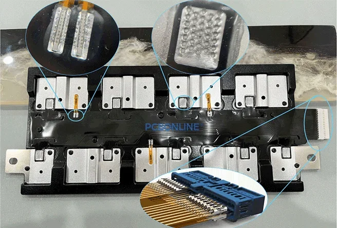
For automotive battery pack projects, PCBONLINE provides FDC (flexible die-cut) as a third flexible interconnect option. An FDC uses die-cut copper foil laminated between insulating films in place of etched circuits, so it costs less than an FPC of the same outline and still bends as the pack requires.
We customize FDC for battery pack CCS (cell contact systems) from prototypes to bulk production.
For FDC connectors, we design and manufacture customized pierce-crimp terminals. The terminal blade pierces the insulating film and presses into the copper conductor, so the contact is a stable metal-to-metal joint without film stripping or soldering.
Because we provide all three options, FPC with stiffeners, rigid-flex PCBs, and FDC, our engineers can quote the most economical construction for your device.
PCBONLINE: Turnkey Partner for Flexible and Rigid-flex PCBs
For terminal companies that require flexible and rigid-flexPCBs with the production flexibility of a turnkey partner, PCBONLINE is the strategic manufacturing partner.
We provide turnkey PCBA manufacturing, including PCB manufacturing, component sourcing, and PCB assembly. Founded in 2005, PCBONLINE has an FCCL factory, two advanced PCB manufacturing bases, and a turnkey PCB assembly factory, with stable supply chains and experienced engineers.
PCBONLINE has turnkey flex and rigid-flex PCB fabrication and assembly capabilities. We not only provide FPC, FDC, and rigid-flex PCBs, but also manufacture flex copper-clad laminates for them.
Powerful FPC and rigid-flex PCB manufacturing capabilities, including transparent PET FPC, 1- to 6-layer FPCs, 2- to 30-layer rigid-flex PCBs, and HDI 4+N+4 rigid-flex.
PCBONLINE can add FR4, PI, and stainless steel stiffeners, electromagnetic films, double-sided tapes, and metal domes to PI and PET flexible PCBs.
PCBONLINE has battery pack CCS R&D capabilities and can do the CCS design or take part in your battery pack project's development from the early stage.
PCBONLINE provides free DFM (design for manufacturing) and one-on-one engineering support for FPC and rigid-flex projects, including FPC layout optimization.
High-quality flexible and rigid-flex PCB assembly certified with ISO 9001:2015, ISO 14001:2015, IATF 16949:2016, RoHS, REACH, UL, and IPC-A-610 Class 2/3.
We not only manufacture PCBAs but also solve any issues to ensure the project goes smoothly. We look forward to becoming a manufacturing partner for OEM companies, terminal product companies, and solution companies. To get a quote for your project, please contact info@pcbonline.com.
FAQs
Q: What is PCBA DFM?For a single connector or component area that only sees static load or occasional bending, yes, and the stiffened FPC costs less. The two are not interchangeable when the design needs vias routed directly between rigid and flex regions, repeated dynamic bending near the component zone, or more than six layers. A stiffener is a mechanical add-on bonded after fabrication, so it cannot provide the electrical integration of a laminated rigid-flex PCB.
Q: What is the cheapest stiffener material for an FPC?FR4 is the cheapest option, bonded with thermoset adhesive, and works for most consumer products. However, punched FR4 edges can carry burrs. PI stiffeners cost slightly more and hold tighter outline tolerances for space-constrained enclosures. Stainless steel costs the most and provides the highest strength and flatness for heavy connectors and repeated mating cycles.
Q: Can rigid-flex PCBs use PET film in the flexible layers?No. PET film melts at the temperature required to laminate FR4 outer layers, so the lamination would destroy the flexible core. Polyimide withstands the lamination heat, bonds reliably with FR4 prepreg, and delivers the bend endurance the product needs.
Q: How many layers can a rigid-flex PCB have?At PCBONLINE, rigid-flex PCBs run from 2 to 30 layers. For dense designs, we build HDI rigid-flex stack-ups up to 4+N+4 with blind, buried, staggered, and stacked microvias.
What is FDC, and when is it used instead of FPC?FDC (flexible die-cut) replaces the etched copper traces of an FPC with die-cut copper foil laminated between insulating films. Automakers use it in high-volume battery pack CCS when the unit cost of the flexible interconnect matters more than fine-pitch routing. For FDC connectors, PCBONLINE provides customized pierce-crimp terminals that pierce the insulating film and press directly into the conductor.
Does PCBONLINE manufacture FPC stiffeners and rigid-flex PCBs in the same factory?Yes. Our Jiangsu manufacturing base runs flexible PCB lines, FR4 rigid PCB lines, laser routing, and ENIG and electrolytic gold plating lines in one facility, so we outsource no rigid-flex process step. We cover prototypes to bulk production, and we can add SMT assembly to the same order. We also build FDC for automotive battery pack CCS.


