
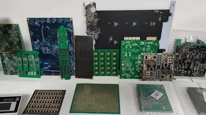
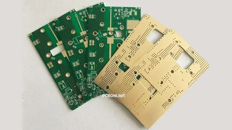
Rigid printed circuit boards (PCBs) are used in almost all electronic products, from consumer gadgets and automotive modules to high-frequency radar and power electronics. PCBONLINE, an OEM PCB manufacturer, provides all types of printed circuit boards. In this article, we provide a comprehensive comparison of the rigid PCBs: FR4 PCBs, aluminum PCBs, copper-core PCBs, PTFE/Rogers high-frequency PCBs, and ceramic PCBs, including Al₂O₃ and AlN.
By comparing dielectric properties, thermal performance, mechanical behavior, and typical applications, this article helps you understand which rigid circuit board is best suited for your design requirements.
Introduction to Rigid PCBs
First, let's see a comparison table of FR4 PCBs, aluminum PCBs, copper-core PCBs, PTFE/Rogers high-frequency PCBs, and ceramic PCBs.
|
Rigid circuit board
|
Thermal conductivity
|
Dk
|
Moisture absorption
|
Best for
|
|
FR4 PCB
|
0.3–0.4 W/m·K
|
4.2–4.8
|
0.10%–0.20%
|
General electronics
|
|
Aluminum PCB
|
1–3 W/m·K
|
~4.0
|
<0.1%
|
LED, power circuits
|
|
Copper-core PCB
|
Copper: ~400 W/m·K
|
3.5–4.5
|
<0.1%
|
High-power electronics
|
|
PTFE/Rogers PCB
|
0.2–1.0 W/m·K
|
2.17–3.5
|
0.02–0.06%
|
RF, microwave, 5G
|
|
Ceramic (Al₂O₃ / AlN) PCB
|
20–170 W/m·K
|
8.5–9.8
|
≈0
|
Power modules, high reliability
|
Rigid circuit boards are defined by their solid, non-flexible substrate layers. This rigidity ensures dimensional stability, allows controlled impedance routing, supports heavy components, and withstands mechanical stress.
While FR4 remains the most popular substrate, alternative materials are increasingly used for high-frequency, high-power, or extreme-environment applications. The choice of substrate affects:
- Dielectric constant (Dk) and signal integrity
- Thermal conductivity and heat dissipation
- Glass transition temperature (Tg) and reliability under thermal cycling
- Moisture absorption, dimensional changes, and insulation quality
- Cost, manufacturability, and layer stackup options
Each rigid PCB material offers a different balance of these characteristics.
FR4 Rigid PCB
FR4 PCB properties include:
- Dielectric constant (Dk): 4.2–4.8 @ 1 GHz
- Dissipation factor (Df): 0.015–0.02
- Tg: 130–140°C (standard), 150–180°C (high-Tg PCB)
- Thermal conductivity: about 0.3–0.4 W/m·K
- Moisture absorption: 0.10% – 0.20%
Advantages of FR4 PCBs include:
- Extremely cost-effective
- Universally supported in PCB fabrication
- Mechanically strong
- Supports high-density multilayers
- Good insulation reliability
Limitations of FR4 PCBs are:
- Poor thermal conductivity
- Moderate dielectric performance unsuitable for RF > 3–6 GHz
- Moisture absorption impacts impedance stability
- Not ideal for high-power or high-frequency applications
Applications of FR4 PCBs include:
- Consumer electronics
- Industrial control boards
- Automotive ECUs (non-power sections)
- IoT devices
- General digital and analog circuits
Aluminum-Based Metal Core PCBs (MCPCB)
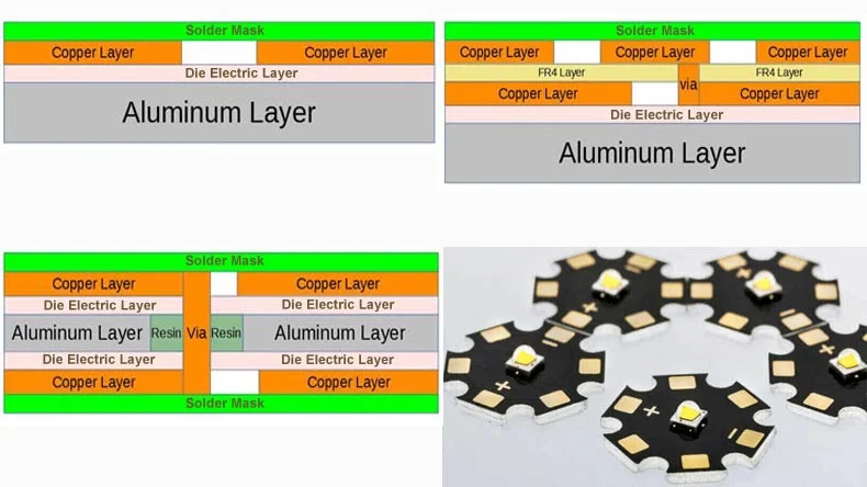
Aluminum PCBs consist of a single copper layer, a dielectric insulation layer, and an aluminum heat-spreader base. Their main purpose is moderate-to-high heat dissipation at low cost. They are widely used in LED lighting, power modules, and DC-DC converters.
Aluminum PCB properties include:
- Tg: 120°C – 150°C (determined by the dielectric layer
- Thermal conductivity (insulation layer): 1–3 W/m·K (standard), up to 5–8 W/m·K (enhanced)
- Thermal conductivity (aluminum base): ~205 W/m·K
- Dielectric constant: ~4.0
- Moisture absorption: <0.10%
Advantages of aluminum PCBs include:
- Excellent cost-to-performance ratio in thermal management
- Lightweight compared to copper base plates
- Good mechanical rigidity
- Suitable for medium-power applications
Limitations of aluminum PCBs are:
- Typically limited to 1–2 layers (not multilayer friendly)
- Dielectric layer determines thermal bottleneck
- Not suitable for high-frequency RF applications
- Lower thermal conductivity than copper-based PCBs
Applications of aluminum PCBs include:
- LED lighting modules
- DC-DC power converters
- Motor drivers
- Automotive lighting (headlamp, daytime running lamps)
- Consumer power electronics
Copper-Based Metal Core PCBs
Copper-based PCBs share the same structure as aluminum MCPCBs but replace the base with copper for extreme heat dissipation capabilities. They are used where thermal performance is critical, such as high-power laser drivers, RF power amplifiers, high-current battery management, and power semiconductor modules.
Copper-core PCB properties include:
- Tg: 120°C – 150°C (depends on insulation layer)
- Thermal conductivity (copper base): ~390–400 W/m·K
- Thermal conductivity (insulation layer): 2W/m·K – 10W/m·K
- Dielectric constant: 3.5–4.5
- Moisture absorption: <0.10%
Advantages of copper-core PCBs include:
- Superior heat dissipation compared to aluminum MCPCBs
- Supports very high currents and power densities
- High mechanical strength
- Suitable for power electronics requiring robust thermal paths
Limitations of copper-core PCBs are:
- Higher cost
- Heavier than aluminum
- Limited layer count up to 8
- Not suitable for complex multilayer routing
Applications of copper-core PCBs include:
- High-power LED arrays
- Laser diode drivers
- IGBT/ MOSFET power modules
- High-current BMS systems
- RF power amplifiers
PTFE/Rogers High-Frequency PCBs
High-frequency PCBs use PTFE-based laminates, such as Rogers RO4003C, RO4350B, and RO5880, which are engineered specifically for RF, microwave, and high-speed digital applications. PTFE itself has an extremely low dielectric constant and dissipation factor, but it is mechanically soft. Therefore, ceramic fillers and woven glass are added for stability.
High-frequency PCB properties include:
- Dk: 2.17 (PTFE) to ~3.5 (Rogers RO4350B)
- Df: 0.0009–0.003
- Tg: >200°C (PTFE does not have traditional Tg limits)
- Thermal conductivity: 0.20–0.40 W/m·K (pure PTFE)
0.6–1.0 W/m·K (ceramic-filled PTFE) - Moisture absorption: 0.02% – 0.06%
Advantages of high-frequency PCBs include:
- Ultra-stable dielectric properties over frequency and temperature
- Very low loss (Df) ideal for high-frequency transmission lines
- Excellent impedance control
- High thermal resistance
Limitations of high-frequency PCBs are:
- Higher cost than FR4
- PTFE PCBs require specialized fabrication processes
- Softer materials may require custom via plating techniques
- Lower mechanical rigidity compared to FR4
Applications of high-frequency PCBs include:
- 5G base stations
- High-frequency radar (24 GHz, 77 GHz automotive radar)
- Satellite & aerospace communication
- High-speed backplanes > 10–28 Gbps
- Millimeter-wave modules
Ceramic PCBs (Al₂O₃ and AlN)
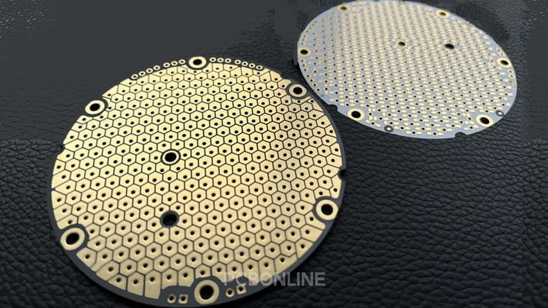
Ceramic PCBs use Aluminum Oxide (Al₂O₃) or Aluminum Nitride (AlN) substrates with thick-film or direct-bonded copper (DBC) metallization. They deliver exceptional thermal conductivity, zero moisture absorption, and excellent insulation performance, making them ideal for high-power and high-reliability applications.
Al₂O₃ (alumina) PCB properties include:
- Thermal Conductivity: 20–30 W/m·K
- Dk: 9.0–9.8
- Moisture Absorption: ≈0
- Cost: Lower than AlN
AlN (aluminum nitride) PCB properties include:
- Thermal Conductivity: 120W/m·K – 170W/m·K
- Dk: 8.5–9.0
- Moisture Absorption: ≈0
- Cost: Higher, premium material
Advantages of ceramic PCBs include:
- Highest thermal conductivity among PCB materials
- Excellent electrical insulation
- Zero moisture absorption
- Very high mechanical and thermal reliability
- Compatible with DBC, AMB, thick-film printing
Limitations of ceramic PCBs are:
- More expensive than FR4 and MCPCBs
- Limited to specific manufacturing processes
- Lower Dk variability options compared to PTFE
Applications of ceramic PCBs include:
- Power modules (IGBT, SiC, GaN)
- Automotive powertrain electronics
- Aerospace and military high-reliability modules
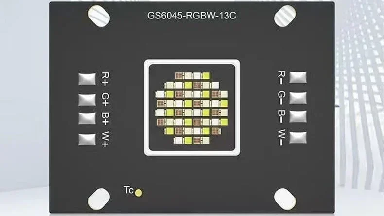
- Laser drivers and high-power LEDs
- High-voltage isolation circuits
Choosing the Right Rigid Circuit Board
When selecting the best substrate for your product design, you should prioritize these questions:
1. What is the operating frequency?
3–30 GHz → Rogers/PTFE
30 GHz → PTFE or specialized ceramic RF substrates
2. What are the thermal requirements?
Mild (consumer electronics) → FR4
Moderate (LED, chargers) → Aluminum MCPCB
Severe (laser drivers, power MOSFETs) → Copper MCPCB or ceramic
3. Is dimensional stability critical?
High-precision RF → PTFE/Rogers
High-power reliability → Ceramic
4. What is the project budget?
FR4 is the cheapest
Aluminum MCPCB is moderate
PTFE, copper, and ceramic are premium materials
Partner with PCBONLINE for OEM PCB Manufacturing
If you are looking for turnkey electronic manufacturing for your PCB project, whether flexible, rigid, or rigid-flex, you can choose PCBONLINE for OEM manufacturing. PCBONLINE provides PCB manufacturing and assembly from prototyping to large-scale manufacturing under one roof.
PCBONLINE has R&D capabilities and provides free DFM and one-on-one engineering support throughout the PCB OEM project.
One-stop OEM PCB manufacturing custom meeting your project's demands, covering hardware and software R&D, prototyping/sampling, PCB fabrication, component sourcing, PCB assembly, value-added, and box-build assembly.
PCBONLINE offers free prototype/samples, R&D, and PCBA functional testing for mass production OEM PCB projects.
High-quality OEM PCB manufacturing certified with ISO 9001:2015, ISO 14001:2015, IATF 16949:2016, RoHS, REACH, UL, and IPC-A-610 Class 2/3.
PCBONLINE will ensure the success of your project, solve all issues, and provide smooth OEM PCB manufacturing.
No matter what application your project will be used for, such as automotive, industrial control, medical, military, aerospace, communication, computer, etc, you can work with PCBONLINE. To reach out to the OEM PCB manufacturer PCBONLINE, contact info@pcbonline.com.
Conclusion
Rigid PCB materials significantly influence the electrical, thermal, and mechanical performance of electronic systems. While FR4 continues to dominate mainstream electronics, applications involving high power, high frequency, or extreme reliability demand alternatives such as aluminum MCPCBs, copper MCPCBs, PTFE/Rogers materials, and ceramic substrates. If you want to order or consult about rigid circuit boards, don't hesitate to contact PCBONLINE.
PCB fabrication at PCBONLINE.pdf


