
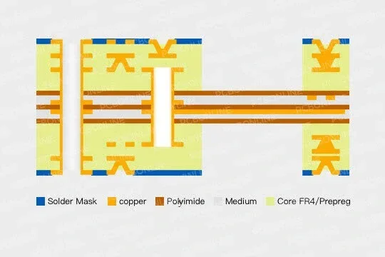
In printed circuit board (PCB) substrate material options, there are FR4, aluminum, copper, ceramics, polyimide (PI), polyester (PET), and PTFE. Among them, FR4 PCB, aluminum PCB, copper-core PCB, ceramic PCB, and PTFE PCBs are rigid, while PI and PET-based PCBs are flexible, including the rigid-flex PCBs using PI + FR4.
Choosing the right PCB, rigid or flexible, is an important design decision in any electronics project. PCBONLINE, an OEM PCB manufacturer, provides both rigid and flexible PCB manufacturing and assembly. In this article, we will learn when to choose rigid or flex PCBs and which is best for your project.
Flexible PCB vs Rigid PCB
Flexible PCBs are used for compact devices that require a lightweight design. Rigid PCBs are used for far more applications. Understanding their differences will help you pick the best option for your design.
Structural differences
Rigid PCBs are made from solid, inflexible materials, most commonly FR-4, a fiberglass-epoxy laminate. They are flat and sturdy and cannot bend without damage. Their advantages include:
- Mechanical strength: Ideal for supporting SMT and THT components.
- Better heat dissipation: Can handle high-power components when designed with thermal vias or heat sinks.
- High-layer counts: Easily supports 4-layer to 40-layer designs for complex routing.
- 3D design capability: Flex parts can fold and wrap around enclosures.
- Shock and vibration resistant: Better mechanical robustness in harsh environments.
Flexible PCBs use thin polyimide (PI) or polyester (PET) films, allowing them to bend, fold, or wrap inside tight spaces. They are pliable and suitable for dynamic or static bending. Their advantages include:
- Space and weight savings: Perfect for wearables, medical, and aerospace products.
- Reducing connectors and wiring between modules.
- Dynamic performance: Handles repeated flexing in moving parts like printer heads or laptop hinges.
Material and performance comparison
The rigid and flexible PCB substrate materials are listed below.
|
PCB material
|
Dielectric constant (Dk) at 1GHz
|
Thermal endurance Tg (°C)
|
Moisture absorption (%)
|
PCB rigid or flex
|
|
Standard FR4
|
4.2 - 4.8
|
130 - 180
|
0.10 - 0.20
|
Rigid
|
|
High-Tg FR4
|
4.2 - 4.4
|
170 - 185
|
0.10 - 0.15
|
Rigid
|
|
Standard PI
|
3.2 - 3.5
|
≥250
|
0.50 - 1.0
|
Flexible
|
|
PTFE
|
2.1 - 2.7
|
200 - 260
|
0.01 - 0.05
|
Rigid
|
|
FR4 + PI
|
FR4: 4.2 - 4.4
PI: 3.2 - 3.5 |
FR4: 150 - 180
PI: ≥250 |
0.1 - 0.6
|
Flexible
|
|
Ceramic
|
Al₂O₃: 9.0 - 9.8
AlN: 8.5 - 9.0 |
>600
|
≈0
|
Rigid
|
For high-frequency or RF designs, rigid PCBs need low-loss PTFE laminates like Rogers 3000/4000 series or ceramic PCBs. Flexible PCBs also provide low loss and excellent signal integrity, and they can be used for antennas and RF interconnects.
Manufacturing and cost factors
Rigid PCBs can support many layers and tight tolerances. If rigid PCB manufacturing uses standard materials of a high production volume, its cost is the lowest per area. Rigid PCB manufacturing costs increase with layer count and circuit density or the use of ceramic or PTFE materials.
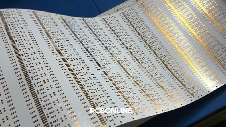
The flexible PCB manufacturing process is more complex than the FR4 PCB. It requires vacuum lamination and precise alignment, and needs coverlay for protection and stiffeners to support component areas. The flex materials, yield rate, and handling complexity drive up the flexible PCB price.
If it is a rigid-flex PCB combining a hybrid stackup of rigid and flexible PCB layers, it offers superior reliability and space efficiency, but at the highest cost and design complexity.
Assembly and rework
Rigid PCBs are easy for automated surface-mount assembly (SMT). They are stable during reflow and are easy to repair or replace fine-pitch parts like BGAs. They also handle high thermal and mechanical stress well.
Flexible PCBs require customized fixtures to hold them flat during assembly. They must be handled carefully to prevent creasing. Rework of flexible PCBs is challenging, as thin copper layers are sensitive to heat and stress, increasing rthe isk of delamination.
Choosing the Rigid or Flex PCB for Your Application?
Choose rigid PCBs when:
- Cost efficiency is crucial (high-volume consumer or commercial products).
- Thermal management is a priority (power supplies, LED boards).
- High layer count and density are required (servers, routers, test equipment).
- Mechanical strength is needed (automotive control units, large enclosures).
Choose flexible PCBs when:
- Your design requires 3D or curved layouts (wearables, cameras).
- Size and weight reduction are essential (medical, aerospace).
- Circuits must move or flex repeatedly (hinges, gimbals).
- You need higher reliability and fewer connectors.
- You're working on RF or high-frequency circuits where low Dk and Df are beneficial.
The choice between a Rigid PCB and a Flexible PCB depends on your project's priorities:
Rigid PCBs are best for cost-sensitive, high-layer, high-power, and mechanically robust designs.
Flexible PCBs excel in miniaturized, lightweight, and dynamic applications that demand superior reliability and space optimization.
If your product combines both rigid areas for components and flexible connections, consider a rigid-flex PCB. While more expensive, it can simplify assembly, reduce connectors, and enhance long-term reliability.
Densign Tips for Rigid and Flex PCBs
Design tips for flex PCB designs:
- Bend radius: Respect the minimum bend radius (depends on thickness and layers).
- Trace layout: Route traces perpendicular to bends to avoid cracking.
- Copper thickness: Use thin copper (0.5–1 oz) to improve flexibility.
- Avoid sharp corners.
- Use rounded edges to prevent tearing.
- Keep vias away from bends to prevent cracking.
Design tips for rigid PCB designs:
- Robotics: Movable joints and sensor integration benefit from flex PCBs.
- Focus on impedance control for high-speed signals.
- Use proper stackup planning to reduce EMI and noise.
- Place decoupling capacitors near IC power pins for PDN stability.
Partner with PCBONLINE for OEM PCB Manufacturing
If you are looking for turnkey electronic manufacturing for your PCB project, whether flexible, rigid, or rigid-flex, you can choose PCBONLINE for OEM manufacturing. PCBONLINE provides PCB manufacturing and assembly from prototyping to large-scale manufacturing under one roof.
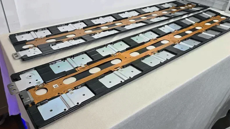
PCBONLINE has powerful rigid-flex PCB capabilities, such as 2-24 layers, HDI 4+N+4, FR4/PI/steel stiffeners.
PCBONLINE offers a free DFM review before production to ensure the manufacturability of the rigid-flex PCB stackup and solve any technical issues.
Our experienced R&D and engineering team provides one-on-one engineering support throughout the project, including rigid-flex PCB stackup optimization.
Turnkey OEM rigid-flex PCB services, including prototyping, PCB fabrication, components, rigid-flex PCB assembly, tests, enclosures, box-build assembly, and value-added services.
High-quality rigid-flex PCB manufacturing certified with ISO 9001:2015, ISO 14001:2015, IATF 16949:2016, RoHS, REACH, UL, and IPC-A-600 Class 2/3.
When your rigid-flex project enters the bulky production stage, PCBONLINE refunds the fees of R&D, prototyping, and PCBA functional testing.
Please take a look at PCBONLINE's capabilities in rigid-flex PCB manufacturing:
|
Features
|
PCBONLINE's Rigid Flex PCB Capabilities
|
|
Layers
|
PCB layers: 2 to 24, flex layers: 1 to 6
|
|
Build time
|
1 day to 4 weeks
|
|
Board size
|
Min. 4mm×4mm to Max. 457mm×610mm
|
|
Final board thickness
|
0.05mm to 0.6mm
|
|
Materials
|
Polyimide, high TG polyimide, FR4, FR4 high TG, RA copper, HTE copper, adhesive
|
|
Flexible PCB thickness
|
0.01mm to 0.15mm
|
|
Min. pitch
|
0.35mm
|
|
HDI stack-up
|
1+N+1, 2+N+2, 3+N+3, 4+N+4
|
|
Aspect ratio
|
1:3
|
|
Copper thickness
|
1/3oz to 3oz
|
|
Min. track/space
|
1.6mil/1.6mil
|
|
Min. mechanical drilling Ø
|
6mil
|
|
Hole size tolerance
|
PTH: ±2mil, NPTH: ±1mil
|
|
Hole position tolerance
|
±2mil
|
|
Surface finishes
|
ENIG: Au 1µ to 5µ", Ni 80µ to 200µ"
OSP
Immersion tin: 0.8µm to 1.2µm
Immersion silver: 0.15µm to 0.45µm
Hard gold plating: Au 1µ to 50u", Ni 80µ to 200µ"
|
Whether you need PCBA manufacturing for flexible, FR4, rigid-flex, RF, or high-thermal-conductivity electronics, PCBONLINE can provide OEM services meeting your requirements. Please feel free to contact PCBONLINE via email at info@pcbonline.com to get a quote.
Conclusion
By understanding rigid PCBs vs flexible PCBs, when to choose rigid or flex PCBs, and design tips, engineers can fully leverage their potential. PCBONLINE is a one-stop rigid and flex PCB manufacturer providing one-on-one engineering support and turnkey electronics manufacturing. If you want to order or consult about rigid or flex PCBs, don't hesitate to contact PCBONLINE.
PCB fabrication at PCBONLINE.pdf


