
Motors are vital to all manufacturing and process industries. Power electronic circuits provide precise, accurate, and efficient control of DC and AC motors. While VFDs provide a good solution for three-phase AC motor speed and direction control, they may be costly for some applications. A less expensive alternative is designing a tailored PLC interfaceable motor control card.
In this article, we will delve into a PLC interfaceable motor control card and its PCB for industrial applications.
Table of contents:
Part 1. Basics of Motor Control Part 2. PLC-Interfaceable Motor Control Cards Part 3. PLC-Interfaceable Motor Control Card and Its PCB: Challenges and Design Considerations Part 4. High-Current PCB Manufacturer for Motor Control CardsBasics of Motor Control
Accurate and precise control of motors is essential for modern industrial machines and equipment. The control strategy varies depending on the type of motor at hand.
For instance, the drive circuit of an AC induction motor is completely different from that of a DC motor.
Similarly, stepper and servo motors use highly sophisticated feedback control circuits for precise motion control applications like industrial robots and CNC machines.
In this article, we will focus on the control of a 3-phase AC induction motor, as it is the most widely used motor in industrial applications.
Traditionally, AC motors were mostly used in constant-speed applications. Varying the speed and torque of an AC induction motor without power electronic converters is not possible, as these parameters depend on the voltage and frequency of the power utility.
However, with the invention of variable frequency drives (VFDs), AC motors are increasingly being used in variable-speed applications.
Typical AC motor control circuits consist of relays, timers, magnetic contactors, thermal overload relays, feedback sensors, and motor protection circuit breakers (MPCBs).
Depending on the cost, application, and size of the AC motor, different control methodologies can be used.
For constant-speed applications where the motor's size is below 5 HP, a basic DOL (Direct-On-Line) or soft starter circuit is sufficient.
In a DOL circuit, 3-phase power is fed to the AC motor through an MPCB and a magnetic contactor.
The basic control circuit consists of one normally open (NO) push-button, one normally closed (NC) emergency stop button, and a magnetic contactor coil (self-holding). This kind of circuit does not offer any provision for direction or speed control.
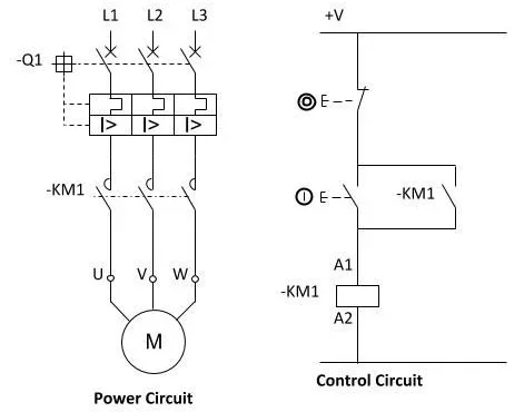
Figure 1: DOL circuit for 3-phase AC motor
For AC motors above 5 HP, inrush current is a major issue.
To address this problem, a star-delta starter is employed.
Initially, the motor runs in a star configuration to restrict the inrush current and starting torque. After a few seconds, the motor is switched to delta configuration to operate at maximum torque. Star-delta starters are typically used for motors rated above 7.5 kW (10 HP).
However, this motor control technique does not provide speed or direction control.
Therefore, it is only appropriate for fixed-speed applications like pumps and compressors.
The star-delta starter consists of one motor protection circuit breaker (MPCB) and three magnetic contactors. One contactor feeds three-phase power to the motor, while the other two contactors are used for switching between the star and delta configurations.
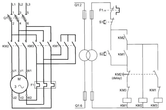
Figure 2: Star-delta starter circuit for 3-phase AC motor
VFDs are versatile power electronic devices used for precise control of speed, torque, and direction of AC motors.
VFDs achieve this functionality by altering the supply voltage and frequency. VFDs offer multiple advantages, including built-in protection features, improved energy efficiency, and programmable motor control. VFDs are commonly used in variable-speed applications such as conveyors, mixers, pumps, and HVAC systems.
The VFD circuit includes rectifier and inverter stages for the supply voltage and frequency regulation. The rectifier stage is used for AC to DC signal conversion.
The DC level of the original DC signal is then varied using a DC-DC converter.
The DC signal from the DC-DC converter is then converted to an AC signal using the inverter.
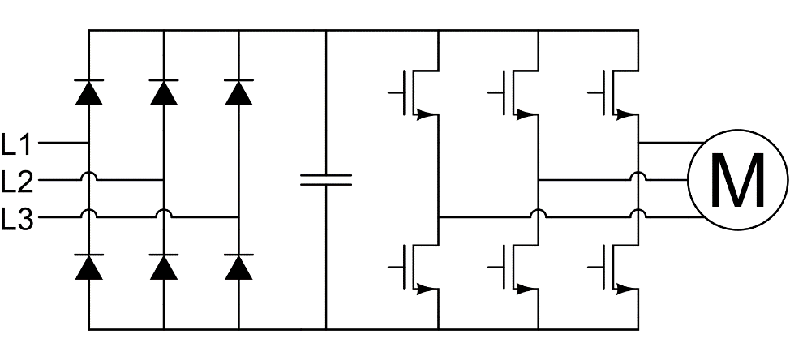
Figure 3: VFD circuit for 3-phase AC motor control
PLC-Interfaceable Motor Control Cards
With the basics of motor controls, now let's focus on the PLC interfaceable motor control PCB.
VFDs offer highly flexible and robust motor control. However, in certain applications, they can be quite expensive and an overkill.
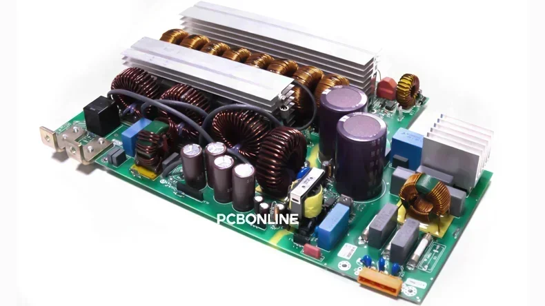
A more cost-effective alternative is a PLC-interfaceable motor control card (MCC).
A PLC interfaceable Motor Control Card is a module designed to control motors, such as start, stop, run, reverse, speed control, and overload protection. The PLC decides what to do, and the MCC acts as the actual motor control. It is essentially a high-current PCB soldered with all the required electronic components, including relays, contactors, motor drivers, and connectors.
The MCC communicates with the PLC through either digital or analog signals to drive the speed and direction of a 3-phase AC motor.
Digital signals are generally used for start, stop, and direction control, whereas speed control is achieved through analog signals (0–10V or 4–20mA).
The control and power stages of the MCC are electrically isolated through relays or optocouplers to ensure safe operation.
Moreover, the MCC includes built-in safety features such as overcurrent, overvoltage, thermal overload, and phase failure protection.
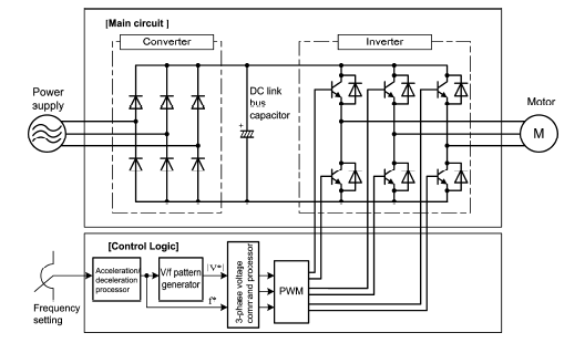
Figure 4: Typical motor control card circuit
PLC-Interfaceable Motor Control Card and Its PCB: Challenges and Design Considerations
PLC interfaceable motor control cards pose multiple design challenges to engineers and circuit designers.
These cards must simultaneously handle low-voltage PLC signals and high-voltage/high-current power signals.
Ensuring galvanic isolation between 24V DC control signals and 400V AC power signals is a key requirement for ensuring circuit safety and reliability.
Additionally, these cards must be rugged enough to operate in harsh industrial environments characterized by shock, vibration, dust, and moisture.
The motor control card (MCC) must also be capable of handling high inrush currents and changing load conditions.
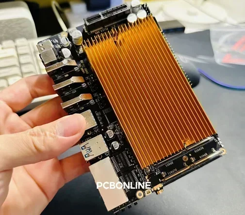
To handle high current and thermal stress, the circuit design typically incorporates heavy-duty magnetic contactors or solid-state relays (SSRs), along with heat sinks, high-Tg FR4 PCB material, wide power traces, and thick copper layers.
Tg is the abbreviation for glass transition temperature, which is the point at which the PCB material changes from a hard, glassy state to a soft, rubbery state.
High-Tg FR4 substrates, with glass transition temperatures above 170°C, offer superior thermal stability under high-load operating conditions.
Thick copper layers and wide power traces allow the circuit to handle higher current flow. Therefore, thick-copper PCBs with a copper thickness of 3oz and above are used as the PCB of the MCC module.
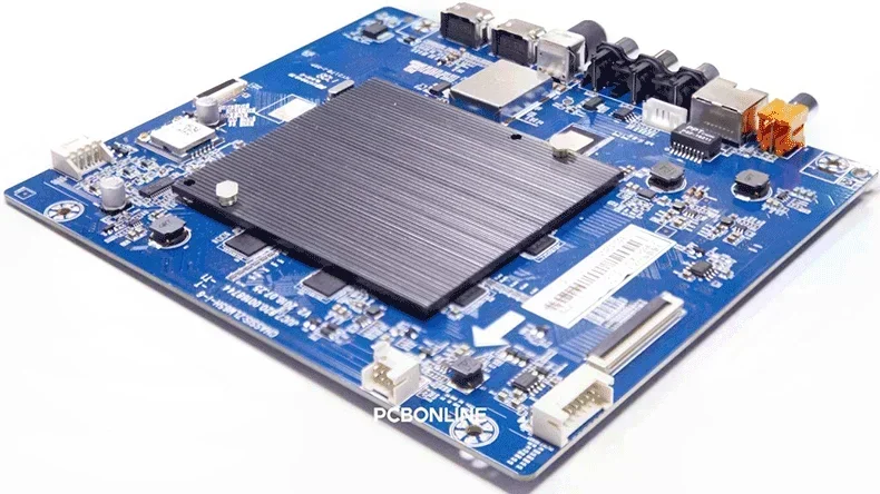
Heat sinks are added to the critical power switching components, such as IGBTs, MOSFETs, or gate driver ICs, to dissipate excess heat effectively.
Furthermore, well-designed PLC interfaceable motor control cards also include intrinsic safety features such as over-voltage protection, over-current protection, phase-failure detection, and thermal overload protection, ensuring reliable and safe motor operation in harsh industrial settings.
High-Current PCB Manufacturer for Motor Control Cards
The critical factors for the PCB of a tailored motor control card are high-current handling, PCB material selection, and thermal performance. To ensure reliable circuit operation under challenging industrial conditions, work with a high-current PCB manufacturer, PCBONLINE, with R&D and EMS (electronic manufacturing service) capabilities to bring your motor control cards into reality.
Founded in 1999, PCBONLINE has two large advanced PCB manufacturing bases for industrial control PCBs, one turnkey PCB assembly factory for high-current PCB assembly and box-build assembly, stable material and component supply chains, strategic cooperation with the mainstream MCU manufacturers, long-term cooperation with the top 3 mold and enclosure manufacturers in China for jigs/textures, molds, and enclosures, and an R&D team for project development and DFM (design for manufacturing).
Powerful PCB manufacturing and assembly capabilities for industrial motor control cards from prototypes to mass production, including high-current PCBs 3oz to 14oz, high-Tg PCBs, PCBs with busbars, etc.
PCBONLINE has rich experience in industrial controls and can do the R&D or take part in the development for your motor control card project, providing the optimum PCB design, reducing fabrication cost.
PCBONLINE pays attention to all details, such as mold/fixture design, reflow/wave oven temperature controls, and fabrication process design, and does well in high-power and high-current PCBs for industrial control applications like motor control cards.
High-quality motor control card PCB/PCBA manufacturing meeting your application demands, including ISO 9001:2015, ISO 14001:2015, IATF 16949:2016, RoHS, REACH, UL, IPC-A-610 Class 2/3, and IPC-A-610 Class 2/3.
When your order goes to the massive production stage, PCBONLINE refunds the fees of R&D, prototyping, components of the prototypes, and offers free PCBA functional testing.
No matter what quantity you want, we always prioritize quality and provide service and support that meet and exceed your expectations.
PCBONLINE has rich R&D and EMS manufacturing experience in industrial control fields, including motor control cards. You can send your project request to PCBONLINE and get a quote by sending emails to info@pcbonline.com.
Extended: History of Motor Control Development
In the early days of the Industrial Revolution, motors quickly displaced steam engines and are still used as the prime movers in industrial machinery. Due to their higher efficiency, easier maintenance, cleaner energy, and compact form factor, motors were rapidly adopted across the board.
During the 3 rdphase of the Industrial Revolution, rapid advances in semiconductor technology facilitated the development of power electronic circuits that enabled the precise torque, motion, and power control of AC and DC motors.
The development of programmable logic controllers (PLCs) and variable frequency drives (VFDs) ushered in a revolution in motor control technology, enabling accurate and efficient control of electric motors. PLC interfaceable motor-control cards enhanced production efficiency, lower energy consumption, and increased reliability.
Conclusion
Motors are the workhorses powering industrial-grade applications and manufacturing plants. Motor-control boards are an integral part of any industrial equipment or process machinery.
The PLC interfaceable motor control card interacts with the PLC's digital and analog I/Os to effectively regulate the speed and direction of the AC motor. Because of increased current ratings, the PCB design has to include high-Tg FR4 material, broader copper traces, and thicker copper layers.
In addition to this, the circuit design must have adequate thermal management and protection features like over-voltage, over-current, and phase failure protection to provide safe and reliable operation of 3-phase AC motors.
To bring your motor control card project to life with reliability and cost-effectiveness, work with the EMS industrial control PCBA manufacturer PCBONLINE.
PCB assembly at PCBONLINE.pdf


