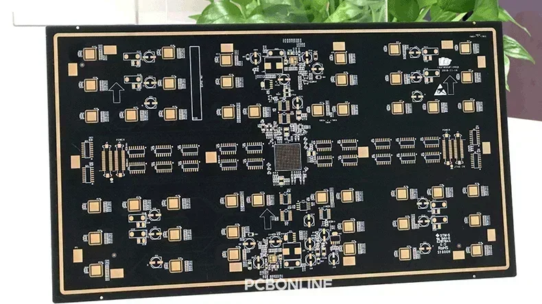
Before PCB (printed circuit board) manufacturing and assembly, DFM (design for manufacturing) is essential. A PCB checklist is a basic requirement for PCB DFM.
A PCB design should meet the application function demands and cater to the PCB industry manufacturing requirements. If you plan for a PCB project, why not have a look at the basic requirements for PCB fabrication?
Below is a PCB checklist used by almost all PCB contract manufacturers.
PCB Checklist
|
PCB checklist item
|
PCB manufacturers' requirements
|
Note
|
|
PCB panel outline
|
length ≤ 450mm, width ≤ 400mm; minimum panel length ≥ 50mm, width ≥ 80mm (in the track's direction
|
This is PCB panelization rather than a single PCB's size requirements.
|
|
PCB thickness: maximum 4.5mm, minimum 0.8mm; using a jig and adding positioning holes to the edge rails is recommended when the PCB thickness is less than 1.0mm.
|
||
|
For PCBs that require only SMT assembly, gaps in the edge are allowed but should be less than 1/3 of the side.
|
||
|
Distance between SMD and edge rails
|
Distance between the SMD's bottom and PCB edge ≥ 5mm;
Distance between the SMD's side and PCB edge ≥ 3mm |
Edge rails, also called break-away, are the sides around the PCB panel for SMT assembly. They are placed on or being clamped by the conveyor of the SMT line.
|
|
If the SMD component is close to and 3mm+ higher than the V-cut, the distance between the SMD and V-cut should be ≥ 1.8mm.
|
||
|
PCB chamfer
|
If the PCB doesn't need to be panelized, the four corners of the PCB should be rounded. If the PCBs need to be panelized, the four corners of the panelized PCB production board should be rounded with a minimum radius of 5mm.
|
Chamfer is the process of creating a beveled edge on the PCB by cutting or grinding the corners of the PCB instead of a sharp 90° corner.
|
|
PCB assembly reflow direction
|
During reflow soldering of the PCB SMT assembly process, the conveyor clamps the long sides of the PCB, and the PCB is reflow soldered in the short side's direction.
|
|
|
Fiducial marks
|
Distance between fiducial marks and edges of the PCB or panelized board > 4.0mm.
|
|
|
If there are ≥ 3 fiducial marks on the panelized board, set no fiducial mark on the edge rail.
|
||
|
If the panelized PCB board's side length is > 368mm, the amount of the fiducial marks is ≥ 5.
|
||
|
Local fiducials should be added near the BGA, whose solder ball space is < 0.8mm, and SOP/QFP, whose pad distance is < 0.5mm.
|
||
|
Component distance
|
Set no SMDs within 1mm from the plug-in components and connectors.
|
|
|
Set no SMD within 1mm near the BGA. For the best effect, set no SMDs with footprint 0805 and above within 3mm near the BGA. Besides, do not place the BGA on the bottom side of the PCB.
|
||
|
If the chip height is ≥ 2.0mm, the component distance should be ≥ 2.0mm.
If the chip height is < 2.0mm, the component distance should be ≤ 0.5mm. The component should not block the solder drag path of the adjacent component. |
||
|
Distance ≥ 2mm between V-cut or half holes and the silkscreen of the SMD component in the vertical direction.
|
||
|
Distance ≥ 1mm between V-cut or half holes and the silkscreen of the SMD components in the parallel direction.
|
||
|
Distance ≥ 2.5mm between the press-fit socket and the ceramic capacitor to prevent the break-out of the ceramic capacitor.
|
||
|
If an SMD, such as a thermistor, needs the glue dosing process to protect it from the environment, leave ≥ 3mm space for dosing glue.
|
||
|
Component placement
|
Place the heavy components such as BGA on the top side of the PCB. If you need to place the heavy component on the bottom side, PCB manufacturers like PCBONLINE have to try and test during the prototype stage before bulk production.
|
|
|
If there's any through-hole component on the top side of the PCB, the bottom side should not have SMD height ≥ 5mm, and for the best effect, SMD on the bottom side height < 3mm.
|
||
|
Set no SMD within 2mm from the short edges of the panelized PCB board's bottom sides.
|
||
|
Set no SMD or through-hole component from the screw-shaped pad of the I/O port to the PCB edge.
|
||
|
All BGAs should be placed on the same side of the PCB, and their direction should be parallel or vertical to the reflow direction.
|
||
|
Place no SMD within 3mm around the through-hole component leads and within 5mm no SMD height ≥ 2.5mm.
|
||
|
Select no through-hole components with a pitch ≤ 1.27mm. It's better to select through-hole components with a pitch ≥ 2.0mm.
|
||
|
On the same side of the PCB, place no SMD with height > 3mm within 3mm from the complaint-pin press-fit component and no SMD within 1.5mm. On the opposite side, place no SMD within 2.5mm from the hole of the complaint-pin press-fit component.
|
||
|
On the same side of the PCB, place no SMD within 1mm from the straight-pin press-fit component. On the opposite side, place no SMD within 2.5mm from the hole of the straight-pin press-fit component. If the hole of the straight-pin press-fit component is installed with a protective cover, place no SMD within 1mm from the cover.
|
||
|
Place the heavy components like BGA near the mechanical support point or edge of the PCB to reduce the PCB warpage.
|
||
|
Design solder-drag pads in the reflow direction for through-hole component leads with a pitch < 2mm.
|
||
|
Component
|
The tolerance of the structural parts should be as close to the PCB tolerance as possible for the precision of positioning holes and PCB grooves.
|
|
|
Select through-hole components for plugins such as USB, HDMI, MIC, Audio, Video, network port, and power supply.
|
||
|
The PCB design should include precautions to prevent plugin errors for connectors with the same PIN.
|
||
|
The direction of the press-fit component should be the same as the reflow direction.
|
||
|
Wiring requirements
|
Distance between the inner/outer circuit lines and the panelized PCB board edge ≥ 0.5mm.
|
|
|
Distance between inner/outer circuit lines and V-cut panelized PCB edge ≥ 1mm.
Distance between inner/outer circuit lines and half-hole panelized PCB edge ≥ 0.5mm. |
||
|
Line width/space ≥ 4mil
|
||
|
For components mounted on two pads, such as resistors and capacitors, the silkscreen line connected to the two pads should be symmetrically led out from the center of the pads, and its width should not exceed 2/3 of the width of the pads.
|
||
|
Place no lines, through holes, and SMD within the contact area of the device's metal enclosure, and the PCB and wiring should be > 1.5mm away from the contact area.
|
||
|
Distance between inner circuit lines and NPTH > 0.5mm.
|
||
|
For through-hole components on the aluminum PCBs, the bond strength of the solder ring around the lead is insufficient, so copper should be added to the solder ring with solder mask applied.
|
||
|
Thermal management design
|
Between two pads of a component, if the line width is large, make the middle of the line a narrow line as the thermal insulation path.
|
|
|
Make the ground pad cross-shaped for large-area power supply.
|
||
|
For a power supply whose temperature goes up more than 30℃, thermal-sensitive components like electrolytic capacitors should be ≥ 4mm away from it if the device is cooled down naturally or ≥ 2.5mm away from it if the device is cooled down with a fan.
|
||
|
Pad wiring
|
If the pads of the SOIC, PLCC, QFP, and SOT are introduced in the circuit, the trace wiring goes from the pads.
|
|
|
Pad design for vias
|
The top of the pad for PCB via is copper-exposed, and the bottom is applied with solder mask.
|
|
|
Screw hole design
|
For mounting screws in a PCB, the hole is designed as a standoff hole with star-moon cutouts and the "star" quantity of 8.
|
|
|
Barcode
|
The barcode is a 30mm x 8mm silk-screen area covered with white PCB ink. No component with height > 25mm within 20mm from it.
|
|
|
Yin-Yang board PCB design
|
Place no SMD through-hole reflow components.
|
|
|
No BGA
|
||
|
PCB layout should be symmetrical
|
||
|
No heavy components
|
A Yin-Yang board is a double-sided PCB with one side for component mounting and routing and the other side for grounding and power distribution.
|
|
|
No components with height > 10mm
|
||
|
No components that can pass only one time of reflow soldering
|
||
|
No QFN with pitch < 0.4mm
|
||
Now, you've gone through the complete PCB checklist before manufacturing and assembly. Great job for you! This checklist is also used by the PCB manufacturers when they view your Gerber and assembly drawing files.
Turnkey PCB Manufacturer Offering DFM for Free to Ensure Your Project Success
You don't need to bother checking your PCB design according to the PB checklist again and again with doubts about your project's manufacturability. To ensure the success of your project, you can work with the one-stop advanced PCB manufacturer PCBONLINE, which offers free DFM before and during prototype and sampling.

Founded in 1999, PCBONLINE has two large advanced PCB manufacturing bases, one EMS (electronic manufacturing services) PCB assembly factory, stable supply chains, and an R&D team to provide product terminal companies, business makers, and research institutes with PCB fabrication, component sourcing, PCB assembly, PCBA value-added, and box-build assembly.
DFM by the one-stop PCBA manufacturer PCBONLINE includes Gerber/BOM/product enclosure checks (the PCB checklist is part of it), manufacturing and testing process design, selecting alternative components with the same functions and certifications to reduce fabrication costs, and solving issues throughout the prototype and product sampling stage.
PCBONLINE can do all the R&D or take part in co-development with your engineers from the early design stage to optimize the project from the PCB design perspective to reduce product fabrication costs and prevent issues in the FAE (field application engineering) stage.
PCBONLINE has powerful PCB manufacturing and assembly capabilities to meet your project demands, from prototypes to mass production.
Comprehensive testing and value-added services in the post-assembly stage to ensure the success of your PCB project, including PCBA functional testing, conformal coating, IC burn-in programming, thermal aging, final product box-build assembly, and application simulation testing.
High-quality manufacturing of PCB, PCBA, and box-builds are traceable and certified with ISO 9001:2015, IATF 16848:2016, RoHS, REACH, UL, and IPC-A-610 Class 3.
No matter what quantity of PCB/PCBA you want, PCBONLINE will offer one-on-one engineering support throughout your project. To get a quote for your PCB project, email info@pcbonline.com.
Conclusion
A PCB checklist used by PCB designers and manufacturers is almost versatile in the electronics manufacturing industry. This blog shows you a comprehensive PCB checklist, which is long and contains a lot of details. However, it is basic and only part of PCB/PCBA DFM. To ensure the success of your PCB project, work with a turnkey PCB manufacturer, PCBONLINE, who offers free DFM, solves unexpected issues, and provides one-stop PCB/PCBA/box-builds from prototypes to scale manufacturing.
PCB fabrication at PCBONLINE.pdf


