
The question "How to read circuit boards" or "How to read schematics" often arises for beginners. Sometimes "What is this component" may also arise. These questions can be solved altogether in this article guiding how to read a circuit board and identify components.
How to Read Circuit Boards - Standards for Electronic Symbols
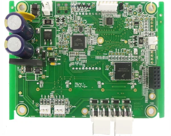
A printed circuit board is a bunch of electronic components interconnected via conductive paths printed on a baseboard. The electronic components and conductive paths are based on a map, the schematic diagram. This diagram is drawn based on widely-accepted rules and symbols.
The symbols used in schematic diagrams are according to standards that are defined at the National and International level by professional organizations, such as the Institute of Electrical and Electronics Engineers (IEEE), the International Electrotechnical Commission (IEC), and the American National Standards Institute (ANSI).
Following are some of the common standards for electronic symbols.
- IEC 60617
- ANSI Y32.2-1975
- IEEE Std 91/91a
![]()
Where to Start Reading Circuit Boards - Power Source
If you have a schematic diagram or a circuit board, the best and easiest way to start analyzing it is from the power source. Every electronic component depends on some sort of power supply. Commonly the designing process of a circuit also begins from there.
The most common type of failure in electronic devices is also power supply failure. Following are the common symbols associated with the power source.
Symbols related to the power source
|
Direct Current (DC) Supply Symbols
|
Alternative Current (AC) Supply Symbols
|
|
|
|
|
Current Source Symbol
|
Battery Symbols
|
|
|
|
|
Controlled Voltage Source
|
Controlled Current Source
|
|
|
|
|
Solar Cell Symbol
|
Ground (Earth) Symbols
|
|
|
|
|
Fuse
|
Transformer
|
|
|
|
The connections within those symbols are shown with lines. And these lines (conductive paths) have joints and crossings. The below symbols represent these.
|
Trace Junction
|
Trace Crossing
|
|
|
|
Reading Schematics - Passive Components
After identifying the power supply, the next most common electronic components are the passive components. The name "passive component" is used for electronic components that cannot inject power or amplify the power in a circuit.
Passive components can only absorb, dissipate, or store energy. These components do not need a set level of voltage (energy) to perform a task.
Common component types that fall into this category are resistors, capacitors, inductors, and transformers.
- Resistors
Resister is a component that acts as a barrier to the current flow. It dissipates energy as heat and creates a voltage drop in the circuit. The resistance value (R) is given in terms of "Ohms", and the voltage drop can be calculated from Ohm's Law Equation.
V = IR
(V = voltage, I = current, and R = resistance)
|
Resistor
|
Variable Resistor (Rheostat)
|
|
|
|
|
Potentiometer
|
Termister or Varistor
|
|
|
|
- Capacitors
Capacitors are components that store energy in an electric field. The capacitance value (C) is given in terms of "Farads". The governing primary equation of capacitors is,
![]()
(C =capacitance, Q = charge in qoulomb, V = Voltage)
|
Unpolarized Capacitor
|
Polarized Capacitor
|
|
|
|
|
Variable Capacitor
|
Trimmer Capacitor
|
|
|
|
- Inductors
Inductors are components that store energy in a magnetic field. Inductance (L) is measured in "Henry". The primary governing equation of Inductors is,
![]()
( Φ = magnetic flux linkage, I = Current, L = Inductance)
|
Air Cored Inductor
|
Magnetic Core Inductor
|
|
|
|
|
Tapped Inductor
|
Ferrite Bead
|
|
|
|
- Transformers
Transformers are used to step up or step down voltages and currents. Energy is transferred in a transformer via a varying magnetic flux. Primary winding induces this magnetic flux, and there are one or many secondary windings that get induced currents from this core magnetic flux. Voltage and current induced here are proportional to the number of turns in the windings.
The governing primary equations of transformers are,
![]()
![]()
(Vp = Primary Winding Voltage, Vs = Secondary Winding Voltage, Np = Number of coils turns in the primary winding, Ns = Number of coils turns in the secondary winding, Ip = Primary Winding Current, Is = Secondary Winding Current.)
|
Transformer
|
Transformer with tapping
|
|
|
|
|
Current Transformer
|
Voltage Transformer
|
|
|
|
- RLC circuits
These are circuits only composed of passive components. These are common in power transmission systems, audio noise filtering systems, EMI filters, and passive frequency filters.
|
EMI Filters
|
Audio Filters
|
|
|
|
Reading Schematics - Common Active Components
Active components are the heart of modern electronics. They are usually made of semiconductors. To perform tasks these components need a set level of voltage or they supply energy to the circuit.
Voltage sources, current sources, generators, all components made of transistors, and all types of diodes are examples of active components.
Let's see some common symbols of active components.
- Transistors
There are tons of transistor types, and each has a unique symbol. Transistor type cannot be determined from its appearance because different types of transistors have the same package type. Transistor type can only be accurately recognized from its model number and symbol. Here we mention some of their most common types.
![]()
|
N-channel junction gate field-effect transistor (JFET)
|
P-channel junction gate field-effect transistor (JFET)
|
Metal-oxide-semiconductor field-effect transistor (MOSFET)
|
|
|
|
|
|
Enhancement mode, N-channel MOSFET
|
Enhancement mode, P-channel MOSFET
|
NPN bipolar junction transistor (BJT)
|
|
|
|
|
|
PNP bipolar junction transistor (BJT)
|
NPN Darlington transistor
|
PNP Darlington transistor
|
|
|
|
|
- Diodes
Diodes are gates that allow current to flow in one direction only. These are commonly used for rectifying AC currents into DC currents in the power supply. Other types of diodes emit light which is called light-emitting diode (LED) and there are diodes that capture light and convert it into a current which is called photodiode. All diodes are made of semiconductors and have a P-N junction.
|
Rectifier Diode
|
Schottky diode
|
Zener diode
|
|
|
|
|
|
Light Emitting Diode (LED)
|
Photodiode
|
Tunnel diode
|
|
|
|
|
|
Varicap diode
|
Shockley diode
|
Silicon-controlled rectifier (SCR)
|
|
|
|
|
|
Constant-current diode
|
Diac
|
Bridge rectifier
|
|
|
|
|
- Integrated Circuits (ICs)
Integrated Circuits (IC) consist of from a few transistors to a few billion transistors. In the modern day, they perform all the main tasks of any circuit. They provide logical computational power, storage, switching tasks, and many more. Integrated circuits are easily identifiable by their package and number of pins. These usually have a higher number of pins than any of the above components. The building block of most ICs is the operational amplifier (opamp). Since there are too many variants of ICs, here we look into only the basic IC symbol which is the OP-AMP.
![]()
|
Operational Amplifier (Op-Amp) or Comparator
|
From Reading Circuit Boards to PCB EMS Manufacturing
Now that you may know how to read a PCB and identify components. It's time to have the PCB manufactured and assembled by a reliable PCB EMS company - PCBONLINE.
PCBONLINE is a one-stop PCB/PCBA manufacturer. Its services include advanced PCB design, PCB manufacturing, electronic component sourcing, PCB assembly, and PCBA value-added services such as conformal coating, and box-build assembly.
If you need more technical assistance, you can also ask PCBONLINE free of charge, whose engineers have dealt with PCB projects for decades.
We provide high-quality advanced PCB boards from prototypes to mass production, including FR4 PCBs of any Tg, FPC, ceramic PCBs, aluminum PCBs, Teflon PCBs, copper-base PCBs, etc.
All products and services are traceable and verified with ISO, IATF, RoHS, UL, and REACH.
Free samples for bulk production, free functional test, and fast delivery.
PCBONLINE's online quote system is open now. Register and get $100 coupons for online PCB purchases. If you need PCBA and box build assembly, please send your inquiry to info@pcbonline.com. The CAM engineer with more than 20 years of experience from PCBONLINE provides one-on-one engineering support and solves technical issues of your project.
Last thing
Now that you can understand how to read schematic diagrams and identify components. PCBONLINE not only provides high-quality PCB manufacturing but also sources all kinds of electronic components according to your BOM. Get a free quotation now!
Related Content:


