
Box-build assembly services refer to one-stop electronics manufacturing services from an initial idea to PCB design, PCBA manufacturing, enclosure, and final device assembly. If you have no R&D capabilities, the box-build assembly service provider PCBONLINE can also develop hardware and software for all your project from scratch. This blog uses a simple project — building a type-C power adapter that gives 5V, 9V, 12V, or 20V output to showcase box-build assembly services.
In this article:
Part 1. Components Used in the Project Part 2. Step-by-Step Process to Design the Project Part 3. FAQs of the Power Adaptor Project Part 4. Tell Your Idea to PCBONLINE for Box-Build Assembly ServicesComponents Used in the Project
This USB-C power adapter uses a USB-C connector and smart circuitry to deliver 5V, 9V, 12V or 20V output. It uses these components:
- CH224K IC: It negotiates power from USB-C.
- DSHP03TS-S switch: It selects output voltage.
- 2-pin screw terminal: It connects to your devices.
- PCB: It is a two-layer printed circuit board.
- Extras: some resistors and capacitors.
Here are explanations for these components used for this project.
CH224K IC: the power negotiator
CH224K is a USB controller and handles USB power delivery (PD), letting the adapter "ask" for higher voltages (like 9V or 12V) from compatible USB-C chargers.
With PD, you unlock faster charging for devices like laptops or drones. Otherwise, the device only works at 5V.
The CH224K is low-cost and supports up to 20V (though we limited it to 12V for safety).
This IC is a USB controller that negotiates voltage/current with compatible chargers. Here's how it works:
Handshake phase: The CH224K communicates with the charger to request specific voltages (5V, 9V, 12V).
Voltage regulation: Once approved, it stabilizes the output for downstream components.
Safety features: Overvoltage, overcurrent, and short-circuit protection.
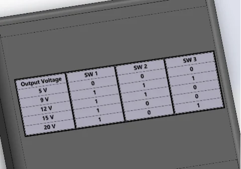
DSHP03TS-S switch module: voltage selector
This 3-switch module lets users pick voltages using binary combinations. Using the schematics in this blog, we will adjust the voltage using the switches by these combinations:
|
Output voltage
|
SW 1
|
SW 2
|
SW 3
|
|
5 V
|
0
|
0
|
0
|
|
9 V
|
1
|
1
|
1
|
|
12 V
|
1
|
1
|
0
|
|
15 V
|
1
|
0
|
0
|
|
20 V
|
1
|
0
|
1
|
USB-C connector & screw terminal
The USB-C connector is the input port for power (works with any USB-C cable).
The 2-pin screw terminal securely connects output wires to your device.
Step-by-Step Process to Design the Project
The complete design process for this type-C power adapter starts from the schematic to the PCBA and the enclosure. If you want R&D for advanced projects for middle and high-end applications, don't hesitate to contact PCBONLINE.
Stage 1: Schematic design
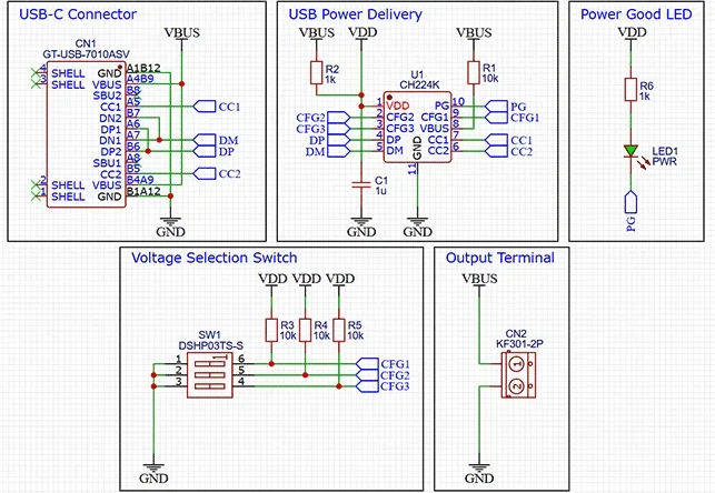
- CH224K setup: Connected to the USB-C port to negotiate voltage (e.g., 5V, 9V).
- Voltage regulation: The CH224K outputs a base voltage, which is then adjusted using resistors and the DSHP03TS-S switch.
- Switch logic: The 3 switches create a binary code to set the final output voltage.
- Capacitors/resistors: Follow the schematics given above and choose the capacitors and resistors of the same value.
- Power LED: It gives us indication about the input power to the Board.
Stage 2: PCB design
For PCB design, you can use any software, such as KiCAD, EasyEDA, etc. Make sure you follow these steps while designing the PCB:
- Adjust the size of your PCB.
- Import a 2-layer PCB to reduce production cost.
- Make sure the components were imported successfully.
- Every component is on the top side (Top Layer) of the PCB.
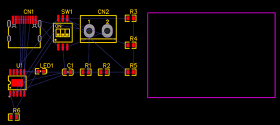
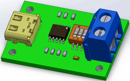
Component placement:
- Place CH224K as close as you can to the USB-C port for clean power negotiation.
- Place the DSHP03TS-S switches for easy user access, which will help us to select the output voltage.
- Place the 2-pin screw terminal at the edge for wiring convenience.
- Add 4 mounting holes on the 4 corners for mounting the PCB onto the enclosure.
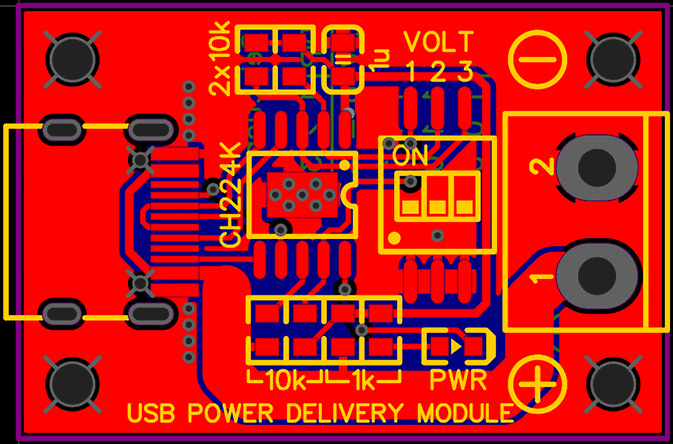
The final PCB layout looks like this:
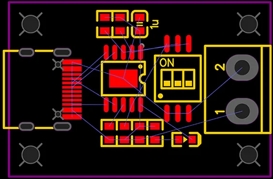
Routing tips:
- Make sure you make all the connections on the Top layer, use fewer vias.
- Thick traces for high-current paths (e.g., 12V output).
- Make sure to make a solid ground plane on the bottom side of the PCB.
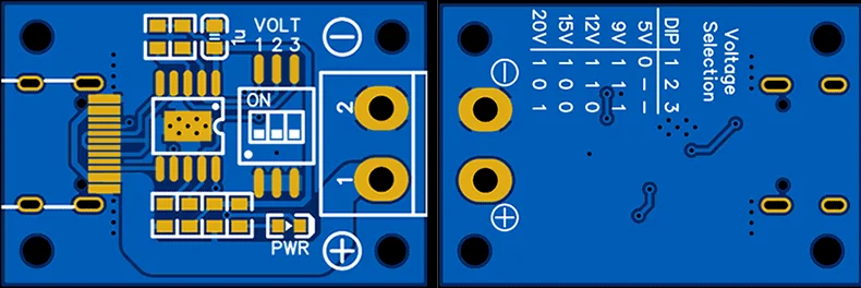
- Also add text on top and bottom solder mask layer.
We have added a voltage selection table on the backside of the PCB. It will help users know the combination of the switches to get their desired output voltage.
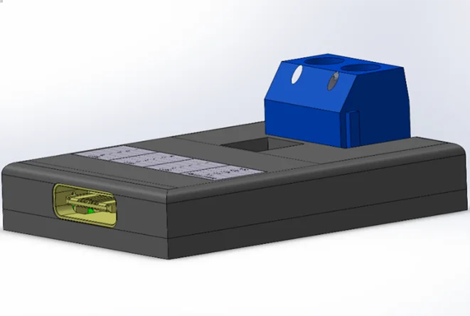
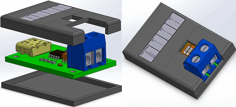
Stage 3: Enclosure design
For the 3D design phase of this simple project, we use SolidWorks. Our aim is to create the enclosure in two parts: the top section and the base. The base will accommodate the PCB, while the top will serve as a lid.
To design the base, the PCB must be imported into our 3D model as a reference. This will allow us to build solid bodies around the PCB according to its dimensions (length, width, and height).
Subsequently, we will design the top section based on the base that we have created.
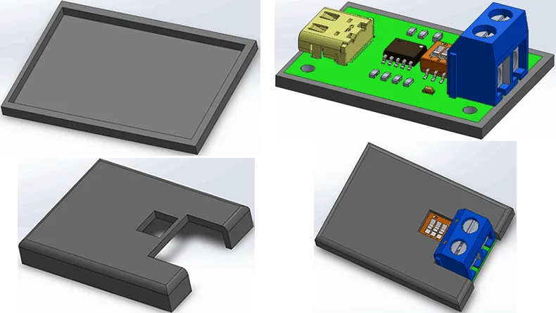
The key considerations in the enclosure design are:
1. Ensure that cutouts are made for the 2-pin screw terminal block to facilitate easy screwing and unscrewing.
2. Create cutouts for the switches to enable voltage changes.
3. Include a cutout for the Type C cable to be plugged into the PCB.
4. You can also add a sticker on the top of the enclosure having the switches combination for the desired voltage output.
The finished power adaptor looks like this:
FAQs of the Power Adaptor Project
Q1: Can I use this with a non-PD USB-C charger?A: Yes, but it'll only output 5V.
Q2: What's the max current at 12V?2A (24W), limited by the CH224K's specs.
Q3: Can I add more voltages? Yes! Modify the resistor network and switch logic. Q4: What are the future upgrades of the project?1. USB-C PD 3.1: We can add Support up to 48V for electric bikes.
2. OLED display: An OLED screen that will show real-time voltage/current.
3. Wireless control: We will be able to adjust voltages via Bluetooth app.
Q5: How to use the power adapter?1. Plug in a USB-C PD charger to the PCB.
2. Set switches to your desired voltage (see label on enclosure or the back of the PCB).
3. Connect your devices to the screw terminal. (Make sure to check the polarity of your device)
4. Ensure that your adapter can deliver multiple voltages. You can confirm by reading the description written on your charger's body.
Q6: What are the real-world applications of the power adaptor?Prototyping labs: Power Arduino (5V), sensors (3.3V), and motors (12V) from one adapter.
Travel: Replace bulky laptop chargers with a compact 12V PD adapter.
Education: Teach students about USB PD and binary logic.
Backpacking: Charge a GPS (5V), power a camping lantern (9V), and run a portable fan (12V) using a single USB-C power bank.
Tell Your Idea to PCBONLINE for Box-Build Assembly Services
This blog only showcases a simple box-build design project. For advanced projects, you can work with the one-stop electronics manufacturer PCBONLINE for box-build assembly, including R&D, PCBA manufacturing, enclosures, and end-device assembly.
R&D and DFM
PCBONNLINE has an R&D team to provide hardware and software development for your project. All you need to do is to provide your initial idea and the key specifications of the product.
If you have part of the R&D capabilities, the engineers from PCBONLINE can take part in your project's development and can reduce your project's production cost with an optimum PCB design.
Before prototyping, PCBONLINE offers free DFM (design for manufacturing) to ensure the manufacturability of your project. We will check the PCB design files (including the Gerber, production file, 3D image, etc.), BOM (bill of materials), and enclosure design comprehensively.
If some components are very expensive for you, we can find affordable alternative components with the same functions and certifications.
Prototyping and sampling
Before bulky production, there's prototyping/sampling to ensure the whole design is error-free and the manufacturing process is smooth.
At PCBONLINE, the PCB prototypes are manufactured on the same lines as bulky production.
If your project goes into the bulky production stage, PCBONLINE will refund the fees of prototyping/sampling and offer free PCBA functional testing.
PCB fabrication, component sourcing, and PCB assembly
PCBONLINE provides advanced PCB manufacturing, including flexible PCBs, HDI PCBs, high-frequency PCBs, ceramic PCBs, rigid-flex PCBs, copper-core PCBs, etc.
The PCB assembly from PCBONLINE includes SMT and PTH assembly. The finest pitch of the SMT assembly is 0.5mm. The advanced equipment, such as 3D solder mask inspection, X-ray inspection, 3D AOI, nitrogen reflow soldering, and selective soldering are available.
Besides, PCBONLINE has stable supply chains for electronic components, with a global supply network, and it can take part in co-procurement with other EMS manufacturers from original component factories.
Enclosures, molds, and box-build assembly
Jigs and molds are required in PCB fabrication and assembly, and box-build assembly requires the enclosures. PCBONLINE has long-term cooperation with the top 3 mold and enclosure factories in China. We will design the jig/mold/stencil precisely meeting the demands for your project's electronics manufacturing process and send it to our partners. If you don't have the enclosure design, we can also design it and have the enclosures manufactured by our partners.
With the PCBAs and enclosures, we will assemble them into the final devices and label according to your requirements. After box-build assembly, we will have the application simulation test to ensure your devices work reliably.
Not only the power adapter shown in this blog, all electronic devices, from consumer electronics to automotive devices, you can send your R&D and manufacturing request to PCBONLINE. To get a quote for your project, please email info@pcbonline.com.
Conclusion
This blog uses a type-C multi-voltage power adaptor project to demonstrate the product design process and box-build assembly services. To ensure the success of your PCBA and box-building projects, work with the EMS PCBA manufacturer PCBONLINE.
PCB assembly at PCBONLINE.pdf


