
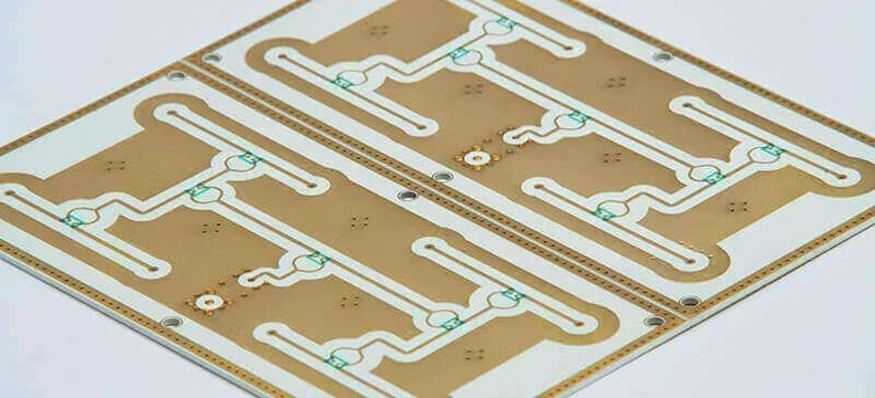
For power electronics and high-frequency telecommunications, the selection of the printed circuit board (PCB) laminate material can impact the performance of the end device. Enter the Rogers ceramic PCB using RO4000 and curamik® laminates, a high-performance solution designed to bridge the gap between structural integrity and superior electrical performance at extreme temperatures.
Rogers Ceramic PCBs handle high-thermal conductivity and high-frequency signals. The RO4000® series for high-frequency signal integrity and the curamik® family for extreme power and thermal management.
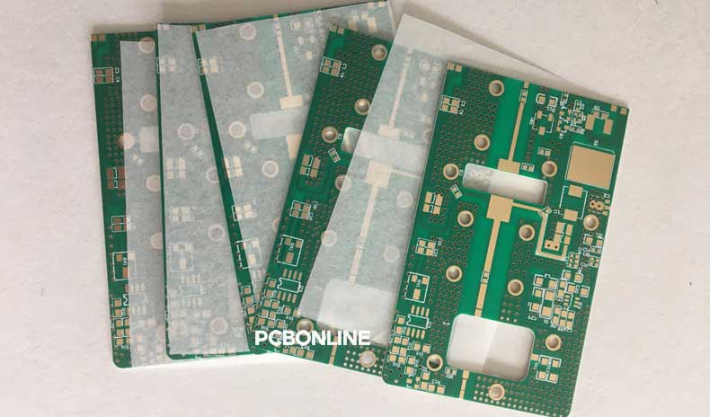
Rogers Ceramic PCB: No Fiberglass, No Compromise
The Rogers curamik® family laminates are Power Substrates built for heat dissipation and reliability. A curamik® Rogers Ceramic PCB has no epoxy or fiberglass at all, and is manufactured with the AMB process.
Architecture and Materials of curamik® Rogers Ceramic PCB
- The base material: curamik® uses a solid and pure ceramic tile, most notably Silicon Nitride (Si3N4). This ceramic base acts as both the high-frequency insulation material and the primary thermal conductor.
- Zero epoxy, zero fiberglass: In a Rogers curamik® Silicon Nitride PCB, there is no epoxy resin and no fiberglass reinforcement. The structural integrity and electrical insulation are provided entirely by the solid ceramic substrate.
- Layer composition: The architecture consists of the Silicon Nitride core, plated with heavy copper and often an aluminum surface coating. This aluminum layer acts as a heat spreader and a protective shield against harsh environments.
The AMB Technology for curamik® Rogers Ceramic PCB Fabrication
Because there is no epoxy to act as a "glue," curamik® Rogers ceramic PCBs require a specialized chemical bonding process called Active Metal Brazing (AMB).
1. Preparation: A solid SiN4 ceramic plate is cleaned.
2. The active element: A brazing alloy containing an "active" metal, Titanium, is placed between the ceramic and the copper foil.
3. Vacuum heating: The ceramic PCB is heated in a vacuum furnace to temperatures near 800°C.
4. Chemical fusion: The Titanium reacts chemically with the ceramic surface, creating a molecular transition layer. This fuses the copper directly to the ceramic, ensuring maximum thermal conductivity and the ability to withstand extreme thermal cycling without delamination.
What are the Features of curamik® Rogers ceramic PCBs?- Extreme thermal conductivity: Reaching up to 90 W/mK, allowing for the highest power density in the industry.
- High fracture toughness: Silicon Nitride is "ceramic steel," offering incredible resistance to mechanical shock and vibration.
- Superior thermal cycling: Can survive thousands of cycles from -55°C to +150°C due to the robust AMB bond.
- Heavy copper integration: Supports ultra-thick copper layers (up to 800µm) for high current carrying capacity.

Primary Applications of curamik® Rogers Ceramic PCB
Due to their massive thermal conductivity and ruggedness, curamik® substrates are found in High-Power sectors.
- Electric vehicle inverters: Managing the heat of SiC (Silicon Carbide) power modules in the drivetrain. For instance, traction inverters, DC-DC converters, and onboard chargers.
- Renewable energy: Power converters for wind turbines and large-scale solar inverters. For instance, high-power solar inverters and wind turbine converters.
- Industrial power: High-voltage motor drives and induction heating systems.
- Aerospace: Power distribution units that must operate in unpressurized, high-temperature environments.
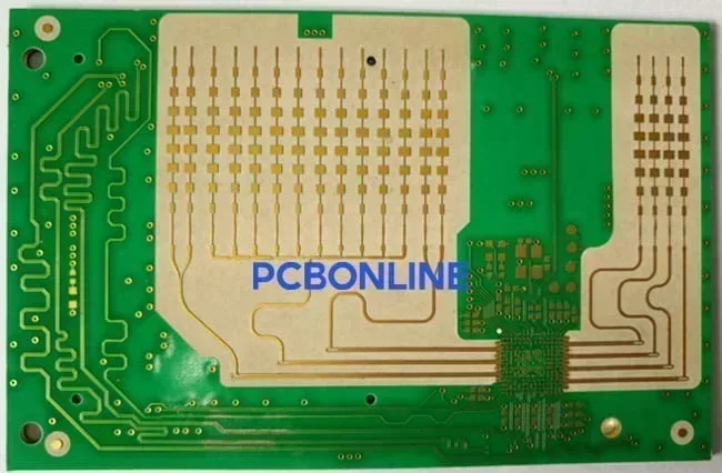
RO4000 Rogers Ceramic PCB: High-Frequency Ceramic Hydrocarbon
In a Rogers FR4 PCB, we must ensure that the Rogers and FR4 materials' thermal expansion, glass transition temperature, and water absorption rate are matched. Failure to do so could result in delamination, warping, or cracking during lamination, reflow soldering, or thermal cycling.
Architecture and Materials of RO4000 Rogers Ceramic PCB
- The dielectric: This is a ceramic-filled hydrocarbon resin. Ceramic in the RO4000 laminate is not a pure ceramic substrate, but microscopic ceramic particles dispersed uniformly throughout a thermoset resin.
- Reinforcement: To ensure dimensional stability and mechanical rigidity, the RO4000 series contains woven fiberglass.
- Construction: The core consists of this ceramic-filled resin, which is then clad with copper using traditional lamination techniques.

Manufacturing Method and Process of Rogers RO4000 ceramic PCB
Unlike curamik® PCBs, which require the AMB process, Rogers RO4000 ceramic PCBs use traditional thermal lamination in PCB fabrication.
- 1. Stack-up: Ceramic-filled hydrocarbon prepregs and cores are stacked with copper foils.
- 2. Lamination: The stack is placed in a vacuum press.
- 3. Heat and pressure: Under high pressure and specific temperature curves (typically 175°C to 250°C), the hydrocarbon resin cures, bonding the layers together.
- 4. Standard processing: Once laminated, the RO4000 PCBs can be drilled, plated, and etched using the same equipment as other rigid PCBs.
However, Rogers high-frequency PCBs all require Plasma cleaning and a thermal shocking test, which is unique among the processes of other PCBs.
- Low dielectric loss: Excellent Df (Dissipation Factor) for minimal signal attenuation at microwave frequencies.
- Stable dielectric constant: Dk remains consistent across a wide range of temperatures and frequencies.
- Low Z-Axis CTE: Matches copper's expansion closely, providing excellent plated through-hole (PTH) reliability.
- Cost-effective fabrication: Most processes are compatible with standard lead-free FR4 PCB processing, reducing the total cost of ownership.
Primary Applications for RO4000 Rogers Ceramic PCB
RO4000 is the industry standard for High-Frequency/Low-Loss sectors.
- 5G infrastructure: Base station antennas and power amplifiers, where signal loss must be minimized.
- Automotive radar: 24GHz and 77GHz collision-avoidance systems.
- Satellite communications: LNBs and ground station equipment.
- High-speed computing: Backplanes and servers requiring low dielectric constant (Dk) tolerances.
RO4000 Rogers Ceramic PCB vs curamik® Rogers Ceramic PCB
RO4000 and curamik® PCBs are both Rogers Ceramic PCBs. When to use RO4000 and when curamik®? The selection between them depends on your choice between Signal Precision and Power Endurance.
Below is a comparison between RO4000 and curamik® Rogers ceramic PCBs.
|
Feature
|
RO4000 series
|
curamik® (Si3N4)
|
|
Material base
|
Ceramic-filled hydrocarbon
|
Solid silicon nitride ceramic
|
|
Bonding tech
|
Thermal lamination
|
Active metal brazing (AMB)
|
|
Epoxy/resin
|
Hydrocarbon resin
|
None (pure ceramic)
|
|
Fiberglass
|
Yes (Reinforced)
|
None
|
|
Thermal conductivity
|
~0.6 to 0.8 W/mK
|
a~90 W/mK
|
|
Copper thickness
|
Standard (0.5oz - 3oz)
|
Ultra-thick (up to 30oz)
|
When to use Rogers RO4000® series? In the RF, microwave, or high-speed digital domain, signal integrity is critical.
- Primary goal: Minimal signal attenuation and stable phase performance.
- Operating frequency: Applications ranging from 500MHz up to 77GHz.
- Manufacturing budget: When you need ceramic-like electrical performance but want to use standard, low-cost PCB fabrication processes (drilling, plating, and etching).
When to use Rogers curamik® family? When dealing with heavy power and extreme heat, that would destroy organic resins.
- Primary goal: Maximum heat dissipation and mechanical ruggedness.
- Current/voltage: Applications handling hundreds of Amps or Kilovolts.
- Thermal environment: When the PCB must survive thousands of rapid thermal cycles (e.g., from -55℃ to +150℃) without delamination.
Partner with PCBONLINE for One-stop Rogers Ceramic PCBs
If you have a project plan for high-power, high-speed, or high-frequency applications, whether you have completed the high-frequency PCB design or not, you can work with the one-stop advanced PCB manufacturer PCBONLINE for turnkey PCB manufacturing, including Rogers ceramic PCBs.

Founded in 2005, PCBONLINE has two large advanced PCB manufacturing bases, one PCB assembly factory, stable supply chains, and an R&D team.
Provide one-stop Rogers ceramic PCB manufacturing, including R&D, prototyping, PCB fabrication, component sourcing, PCB assembly, PCBA value-added, and box-build assembly.
Minimum laser drill: 0.075mm, minimum mechanical drill: 0.15mm, with microvia structures of 100µm and 125µm. High-density circuit layers up to 20, and microvia layers up to 64.
PCBONLINE grasps the core technologies for high-frequency and ceramic PCB manufacturing, such as impedance control, embedded antenna DFM, expansion/contraction control, and AMB/DPC/LTCC/HTCC technologies.
Have ready-to-use high-speed PCB base materials in stock, and the storage period is within 45 days (at manufacturers who have no storage, it usually takes 2 to 3 months to purchase base materials).
Can make various hybrid high-frequency PCBs, including Rogers FR4 PCB and Rogers FR4 ceramic PCB.
High-quality, ceramic high-frequency PCB manufacturing certified with ISO 9001:2015, ISO 14001:2015, IATF 16949:2016, RoHS, REACH, UL, and IPC-A-600 Class 2/3.
PCBONLINE pays attention to quality and cost-effectiveness in high-power, high-frequency PCBs. If you want to get a quote or ask questions about Rogers ceramic PCBs, you can send an email to info@pcbonline.com to get a quote.
Conclusion
The choice between a Rogers RO4000 and a Rogers curamik® PCB is determined by whether the design prioritizes signal or power. The RO4000 series for signal, the curamik® silicon nitride PCB with the AMB technology for high power. If you need Rogers ceramic PCBs or PCBA, work with the one-stop high-frequency PCB manufacturer PCBONLINE.
PCB fabrication at PCBONLINE.pdf


