
The Internet of Things connects things together. The connection can be based on different protocols such as MQTT, AMQP, HTTP, CoAP, LoRaWAN, or Cellular communication. In this blog, we will learn what LoRa communication is, how LoRa is used for P2P (peer-to-peer) wireless communication, and how to make a P2P communication between two LoRa modules using ESP32 by doing a hands-on example.
In this article:
Part 1. What is LoRa for P2P Communication Part 2. LoRa Peer-to-Peer Project Example Part 3: One-stop PCBA Manufacturer for Your LoRa Peer-to-Peer ProjectWhat is LoRa for P2P Communication
LoRa stands for long-range, which is the modulation technique using chirp spread spectrum (CSS). This modulation technique is generally used by LoRaWAN (long-range wireless network) to communicate at long range using minimal energy consumption.
LoRa is highly effective in areas with limited or insufficient WiFi or cellular communication networks, such as remote locations, agricultural fields, and environmental monitoring.
To understand the LoRa P2P communication, it is important to understand the LoRaWAN architecture. LoRa operates in unlicensed sub-GHz frequency bands (e.g., 868 MHz in Europe, 915 MHz in the U.S.), enabling long-range communication with minimal energy consumption.
The architecture of LoRaWAN uses the stars-of-stars topology and consists of End devices, Gateways, Network servers, and Application servers.
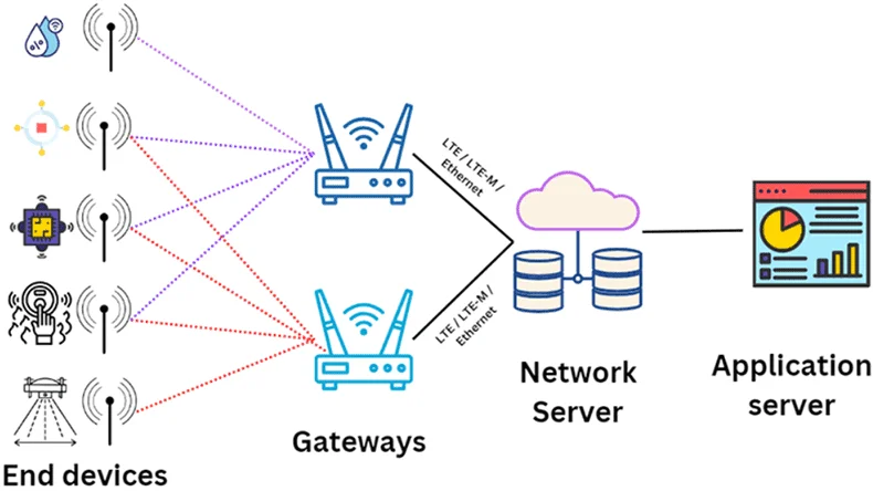
LoRaWAN architecture
In the LoRaWAN architecture, the data flows from End devices to the application server or reversed, but in P2P communication is when two P2P devices communicate with each other or make connections as shown in the following figure, device 1 and device 5 is making a P2P communication.
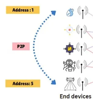
LoRa Peer-to-Peer communication
In the next section, we will use the LoRa module with ESP32 to make a P2P communication using ESP32.
LoRa Peer-to-Peer Project Example
For this example and the demonstration of P2P communication, we will use two LoRa RYLR993 modules and connect them to ESP32. RYLR993 LoRa modules are from REYAX which support multiple frequency bands, low power consumption, and long range.
Interfacing ESP32 with RYLR993 module
The LoRa module is connected to the ESP32 using Serial communication. Both ESP32s will be connected to the RYLR993 module in the following way:
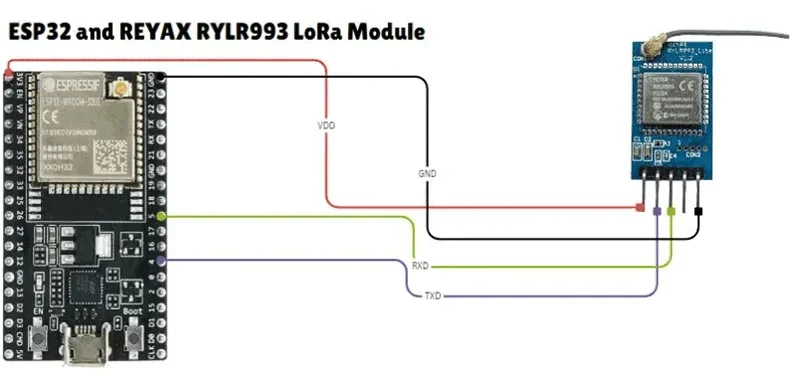
Interfacing ESP32 with RYLR993 module
The connections in the above figure are as follows,
- 3.3V: LoRa module's power supply pin to the 3.3V pin on the ESP32.
- GND: LoRa module's ground pin to the GND pin on the ESP32.
- RX: LoRa module's RX (receive) pin to the D5 pin on the ESP32.
- TX: LoRa module's TX (transmit) pin to the D4 pin on the ESP32.
Next, we will upload the code to both ESP32s using Arduino IDE.
Code Uploading
Then using the Arduino IDE, we will upload the following code to the ESP32s one by one. One ESP32 will be configured with Address 1 and the other with Address 2.
// Include the necessary library
#include <HardwareSerial.h>
// Create an instance of HardwareSerial
HardwareSerial ReyaxLoRaSerial(1);
void sendATCommand(String command, String expectedResponse, unsigned long timeout = 1000) {
ReyaxLoRaSerial.println(command);
unsigned long startTime = millis();
String response = "";
while (millis() - startTime < timeout) {
if (ReyaxLoRaSerial.available()) {
response += (char)ReyaxLoRaSerial.read();
}
if (response.indexOf(expectedResponse) != -1) {
Serial.println("[OK] " + command);
return;
}
}
Serial.println("[ERROR] " + command);
Serial.println("Response: " + response);
}
void setup() {
// Initialize the primary hardware serial port for monitoring
Serial.begin(115200);
Serial.println();
delay(2000);
// Initialize the secondary hardware serial port for communication with Reyax LoRa
// Parameters are (TX pin, RX pin)
ReyaxLoRaSerial.begin(9600, SERIAL_8N1, 4, 5); // Change 4 and 5 to the pins you want to use
delay(1000);
Serial.println("Initializing Reyax LoRa Module...");
// Send AT commands to configure the device
sendATCommand("AT", "OK");
sendATCommand("AT+OPMODE=1", "OK"); // Set to proprietary mode
sendATCommand("AT+ADDRESS=1", "OK"); // Set device address to 1 for device 1 and 2 for device 2
sendATCommand("AT+BAND=923000000", "RESET"); // Set frequency band and expect reset prompt
Serial.println("Reyax LoRa Module Initialized.");
Serial.println("Serial monitor settings:");
Serial.println("- End Char : Newline");
Serial.println("- Baud Rate : 115200");
Serial.println();
}
void loop() {
static unsigned long lastSendTime = 0;
unsigned long currentTime = millis();
// Send a message every 2 minutes
if (currentTime - lastSendTime >= 120000) {
lastSendTime = currentTime;
sendATCommand("AT+SEND=2,30,Hello from Arduino IDE ESP32", "OK"); //change AT+send=1 to send message to device 1 and AT+send=2 to send message to device 2
}
// Read data from ReyaxLoRa and send it to Serial monitor
if (ReyaxLoRaSerial.available()) {
Serial.println(ReyaxLoRaSerial.readString());
}
// Read data from Serial monitor and send it to ReyaxLoRa
if (Serial.available()) {
ReyaxLoRaSerial.print(Serial.readString());
}
}
The above code requires AT commands for setup. AT commands are text-based instructions used to configure communication modules like LoRa, manage settings, and handle data transmission.
To view the received and sent messages, you can use the Arduino Serial monitor.
Note: Make sure to change the address of the device in the code.
sendATCommand("AT+ADDRESS=1", "OK"); // Set device address to 1 for device 1 and 2 for device 2 and make sure to change the device address while sending the message.
sendATCommand("AT+SEND=2,30,Hello from Arduino IDE ESP32", "OK"); //change AT+send=1 to send message to device 1 and AT+send=2 to send message to device 2
This hands-on example demonstrates how two LoRa modules can be used for P2P communication. P2P communication simplifies the system while retaining the key benefits of LoRa technology, such as long-distance connectivity, low power consumption, and enhanced security and privacy.
One-stop PCBA Manufacturer for Your LoRa Peer-to-Peer Project
To bring your LoRa project from an idea or design to real IoT products, you can work with PCBONLINE for one-stop electronics manufacturing, including software and hardware R&D, prototyping/sampling, PCB fabrication, component sourcing, PCB assembly, PCBA value-added, and IoT end-device box-build assembly until the final product delivery.
Founded in 1999, PCBONLINE has two large advanced PCB manufacturing bases, one PCB assembly factory, stable supply chains, and an R&D team. Besides, it has long-term cooperation with China's top 3 mold and enclosure factories for jigs and enclosures for PCB assembly and box-builds. What's more, PCBONLINE has strategic cooperation with mainstream microcontroller companies such as Espressif and Quectel.
PCBONLINE provides free design for manufacturing (DFM) and one-on-one engineering support for LoRa P2P projects.
PCBONLINE has IoT project R&D capabilities and can do the R&D for your LoRa P2P project or take part in your project's development from the early stage.
The IoT PCBs, PCBAs, and box-builds at PCBONLINE have gone through comprehensive tests, such as functional testing, 3D AOI, and application simulation testing.
High-quality IoT PCBA manufacturing certified with ISO 9001:2015, ISO 14001:2015, IATF 16949:2016, RoHS, REACH, UL, and IPC-A-610 Class 2/3.
When your LoRa P2P project goes to bulky production, PCBONLINE refunds the fees of R&D, sampling, and PCBA functional testing.
No matter what quantity of PCBA boards you want for your LoRa Peer-to-Peer project, PCBONLINE can provide turnkey electronics manufacturing from your initial idea to the final IoT devices. To get a quote for your LoRa P2P project, please contact info@pcbonline.com.
Conclusion
This blog introduces the LoRa technique for Peer-to-Peer communication and uses a simple LoRa Peer-to-Peer example, which can be extended with the interfacing of sensors to send real data. If you have questions about your LoRa P2P or any other IoT project, chat with PCBONLINE from the online chat window.
PCB assembly at PCBONLINE.pdf


