
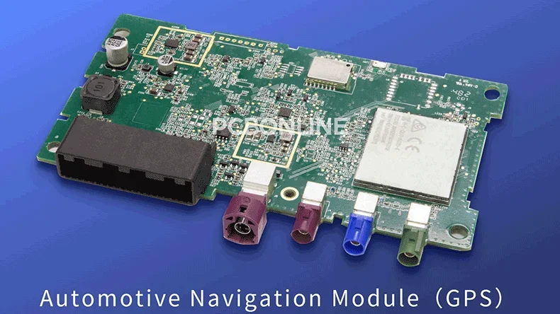
The navigation system is necessary for both electric and oil cars. Even the traditional old models can additionally be equipped with a navigator. In the automotive navigation system, the functional hardware unit is the PCB (printed circuit board), which carries and connects all the electronic components, including the MCU, antenna interfaces, I/O interfaces, capacitors, etc.
PCBONLINE is an OEM PCB manufacturer, providing automotive PCB manufacturing and assembly, including automotive navigation PCBs. In this article, we explain the core technologies behind automotive GNSS/GPS navigation systems and use an automotive GPS module board as an example to analyze its PCB architecture and engineering design.
Core Technologies Used in Automotive GPS PCBs
Although people often say "GPS navigation", automotive navigation systems use more than just GPS. GPS PCBs rely on multiple satellite constellations, sensor fusion, and navigation algorithms.
The GPS is an important system in GNSS (Global Navigation Satellite Systems). Besides the GNSS, assisted positioning is used. Navigation software is also necessary to burn into the IC of the GPS PCB.
Global Navigation Satellite Systems (GNSS)
GNSS refers to all global satellite positioning systems. GPS is only one of them.
The GPS, or Global Positioning System, was developed by the U.S. It calculates position using trilateration. The receiver measures its distance to at least three satellites to find its 2D location (latitude and longitude).

Besides the GPS, automotive navigation PCBs use GNSS receiver chips to support other systems, such as BeiDou (China), GLONASS (Russia), and Galileo (Europe).
Assisted positioning and sensor fusion
Satellite signals are not always reliable, especially in tunnels or between tall buildings. To keep the navigation smooth, GPS PCBs use sensor fusion with an inertial navigation system, also known as dead reckoning. The assisted positioning function includes:
- Inertial measurement unit (IMU): The IMU includes a gyroscope that measures rotation and accelerometers that measure acceleration. By integrating these signals, the system can estimate position, speed, and direction even when satellite data is unavailable.
- Vehicle data interface: The navigation system reads data from the vehicle's CAN bus, such as wheel speed. The information helps calculate the distance traveled more accurately.
Navigation software and engine
The MCU or core IC on the automotive GPS PCB runs advanced navigation software. It includes a navigation engine that uses algorithms such as Dijkstra's or A* to calculate routes. The engine combines GNSS data, map data, and real-time traffic information to provide fast and efficient navigation.
Engineering Analysis of an Automotive GPS PCB

The above circuit board is a GPS PCBA manufactured by PCBONLINE for cars. We use it as an example to show a high-level design of GPS PCBs optimized for low power consumption, EMI control, and strong signal performance in harsh automotive conditions. Its critical components include the main processing unit, edge connectors, and supporting circuitry.
A. Main processing unit (MPU/MCU)
At the center of the GPS PCB is a large component covered by a silver metal shield. It is the main processor, MPU.
It runs the operating system Linux, navigation software, the user interface, and all peripheral controls.
The metal shielding of the main processor serves two purposes: EMI shielding and heat dissipation. It protects the processor's high-speed digital signals and prevents interference with nearby RF components. When the GPS PCB works, the processor generates significant heat. The metal cover also helps spread and transfer heat to a heat sink or the device's chassis.
B. Edge connectors and communication interfaces
The connectors along the edges of the GPS PCB handle power, data, and wireless communication. They are the multi-pin connector, RF antenna interfaces, and I/O and A/V connectors.
- The large component in the top-left area in the above GPS PCB picture is an automotive-grade multi-pin connector. It supplies power from the car battery and carries communication through the CAN or LIN bus.
- The black/white connectors on the PCB edge are RF antenna interfaces. These connect to external antennas for GNSS, 4G/5G, Wi-Fi, and Bluetooth. They are high-frequency connectors such as HSD, FAKRA, or SMA, designed for signal integrity and mechanical stability.
- On the PCB edges, the other smaller connectors are I/O and A/V connectors. They support audio, video (rear camera), USB, SD cards, and data I/O.
C. Supporting circuitry
Components around the example GPS PCB are capacitors and smaller ICs. They ensure clean power delivery and stable signals.
- Capacitors: The silver cylindrical capacitors (electrolytic) and smaller ceramic capacitors smooth out voltage fluctuations and provide decoupling for sensitive ICs.
- Smaller ICs: They include GNSS baseband processors, power management, memory chips, and CAN/LIN transceivers.
Engineering Characteristics of Automotive GNSS PCBs
Automotive navigation PCBs must deal with strong heat output and high-frequency RF signals, so they are high-frequency PCBs that deal with high thermal dissipation. Both require careful PCB design.
Thermal management
Automotive environments have wide temperature ranges. The GPS PCB must prevent overheating, and its thermal management methods include thermal vias, thick copper layers, and ground planes.
- Thermal vias: The processor sits on a thermal pad connected to many small copper-plated vias. These vias move heat to the inner copper layers and the bottom of the PCB.
- Thick copper layers: Using 2 oz or 3 oz copper helps spread heat across the GPS PCB.
- Ground planes: Large internal ground layers act as heat spreaders and route thermal energy toward the chassis.
High-Frequency RF performance
GNSS, cellular, and Wi-Fi signals operate at high frequencies, like 1.575 GHz for GPS L1. Good RF design ensures accuracy and strong signal reception.
- Controlled impedance traces: RF lines, such as those connecting the GNSS chip to the antenna, must maintain a precise 50-Ω impedance. This depends on trace width, PCB thickness, and dielectric constant.
- PCB material selection: Low-loss materials with low Df reduce signal loss at high frequencies.
- RF shielding: Sensitive RF parts like the LNA often have their own shielding or are isolated using ground planes.
- RF trace layout: RF traces must be short and straight. Smooth bends are used instead of sharp corners to reduce signal reflections.
Quality and Acceptance Requirements for Automotive GNSS/GPS PCBs
Automotive GPS modules are classified as safety-relevant electronics. Even if navigation is not directly a safety system like braking or airbags, inaccurate positioning can indirectly affect driving safety.
Therefore, the automotive GPS PCB and PCBA must meet strict automotive-grade quality and reliability standards in addition to IATF 16949:2016.
Besides IATF 16949:2016, the other quality requirements that a car GPS PCB should meet are below.
- AEC-Q100/AEC-Q200:AEC-Q100/AEC-Q200 are qualifications for automotive components used on the automotive GPS PCB. They ensure parts can survive automotive temperature, humidity, vibration, and electrical stress. AEC-Q100 applies to integrated circuits, including the GNSS receiver chip, MPU, and PMIC. AEC-Q200 applies to passive components, including capacitors, inductors, and resistors.
- ISO 16750: ISO 16750 is an environmental testing standard for road vehicles against real automotive conditions. It includes temperature cycling, mechanical shock and vibration, power supply fluctuations and jump-start conditions, chemical exposure, and humidity and thermal shock.
- ISO 11452/CISPR 25: ISO 11452/CISPR 25 ensures electromagnetic compatibility. GPS PCBs include sensitive RF circuits, so EMC requirements are critical.
- IPC standards for manufacturing and acceptance: The acceptance standards of automotive GPS PCBAs include IPC-6012 Class 3A for high-reliability rigid PCBs for automotive/aerospace, IPC-610 Class 3 for acceptability for high-performance electronic assemblies, IPC-2221/2222 for PCB design standards, and IPC-9701 for solder joint reliability testing.
- PPAP (production part approval process) reports: All production steps of GPS PCBA manufacturing are documented. PPAP reports verify process stability and long-term quality.
- RoHS/REACH compliance: RoHS/REACH are mandatory for chemical/material safety, including control of hazardous substances.
Because GNSS modules depend heavily on stable RF performance, automotive navigation PCBs must also meet RF-specific reliability requirements. The GPS PCB design should ensure:
Low-loss PCB materials must remain stable across temperature changes.
Antenna connectors must pass durability testing for vibration and mechanical pull forces.
RF shields must maintain integrity through thermal cycling.
LNA and GNSS front-end circuits must retain sensitivity after environmental stress testing.
Impedance-controlled traces must remain stable after humidity absorption and solder reflow cycles.
Partner with PCBONLINE for Automotive GPS PCB
Since our foundation in 2005, PCBONLINE has been committed to automotive PCB assembly for more than two decades and served end-terminal and design clients from around the globe, including Fortune 500 companies and startups in automotive electronics.
Our automotive PCB assembly services offer:
- Turnkey PCBA manufacturing: From PCB prototypes and testing to mass PCBA and box-build assembly, our PCB assembly services are custom and one-stop.
- Complete procurement: We source and customize enclosures, cables, and accessories from reliable suppliers.
- Engineering support: We check Gerber, BOM, pick-and-place file, and enclosure and accessory designs, and can suggest design changes.
- Free DFM/DFT: We provide free Design for Manufacturability (DFM) and Design for Testability (DFT) checks to ensure that designs are optimized for a smooth production process.
- Quality assurance: IPC-A-610 Class 3, IATF 16919:2016, 4-terminal sensing, and automotive-grade inspection standards.
- Turnkey delivery: From PCB fabrication to final product packaging and shipping.

PCBONLINE manufactures, assembles, and tests automotive PCBs and PCBAs to box builds as a source factory manufacturer from prototypes to bulky production, saving costs and time for you.
We have powerful manufacturing strength for automotive PCBs and assemblies, such as HDI PCBs, high-frequency PCBs, ceramic PCBs, waterproof sealing, and 01005 fine-pitch assembly.
PCBONLINE has robust automotive PCBA capabilities, including speedy delivery for prototypes and small batch orders, and electronic components integration sourcing.
We can precisely control reflow/wave oven temperatures, design PCBA fixtures, and help create user manuals, installation guides, and compliance labels.
Our automotive PCB assembly is certified with ISO 9001:2015, ISO 14001:2015, IATF 16949:2016, RoHS, REACH, UL, and IPC-A-610 Class 3.
Our one-on-one free and professional DFM helps you debug and improve design, to ensure the manufacturability, cost-effectiveness, and final device success.
Send us your BOM, Gerber, and pick-and-place file, and we can bring out turnkey automotive PCB assembly as well as conformal coating, four-terminal sensing, functional test, and value-added services. To get a quote for your automotive GPS PCB/PCBA project, email us at info@pcbonline.com.
Conclusion
An automotive GPS PCB combines high-speed processing, precise RF reception, automotive-grade connectors, and robust thermal management. Partnering with an experienced automotive PCBA manufacturer like PCBONLINE ensures that your GPS PCB offers reliable and accurate navigation performance. Contact PCBONLINE today to discuss your GPS PCB requirements and get professional support
Battery Management System Manufacturing at PCBONLINE.pdf
CCS Product Introduction - PCBONLINE.pdf
PCB assembly at PCBONLINE.pdf


